Ceca air dryer
Three fuel systems are available for use in Cell 3. Two of these
supply fuel at ambient temperature but the third, described in para 3.7, supplies fuel at temperatures up to 250°C. The
capacities of the two ambient systems are 6,000 and 12,000 gal/h at 15 to 100 lb/in2. Both systems operate in a spill
arrangement which enables rapid acceleration tests to be carried out at susbstantially steady supply pressure.
Cell 4 is supplied with fuel from branches in the
Cell 3 6,000 and 12,000 gal/h systems.
Engine operation during transient acceleration cycles can be measured in addition to the usual performance
observations under steady state conditions and for this purpose engien test information is normally fed through an on-line
ICL 1904S* computer. Further details of the data gathering systems are included in Section 4.
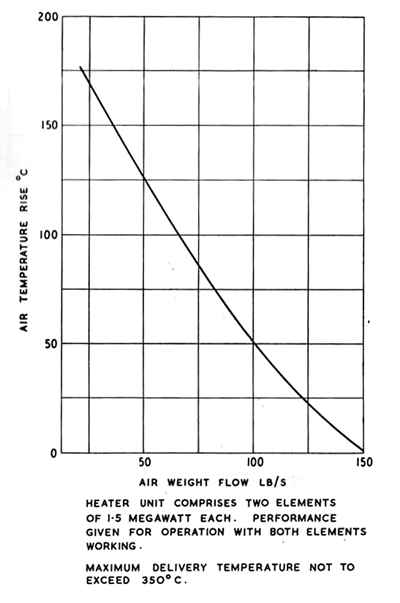
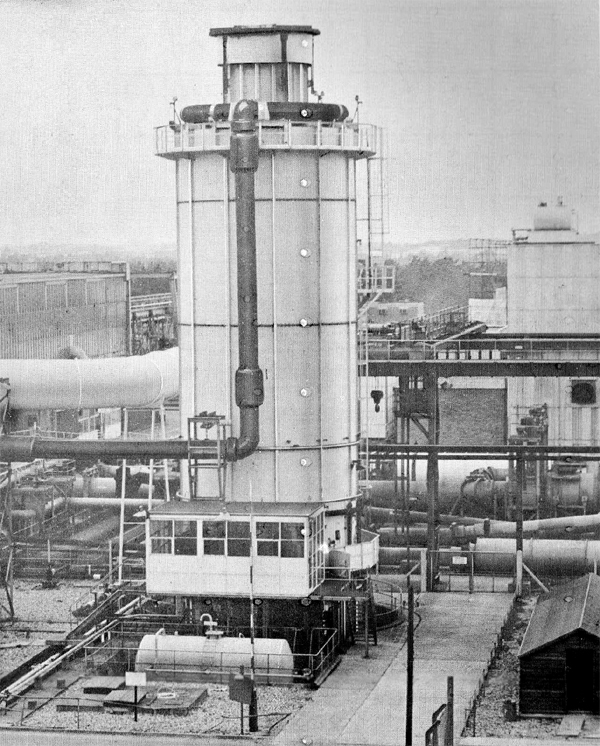
3.4 Cell 3 Air Heating Plant
The Cell 3 heater is shown in Figure 3.21 and consists of a vertical
oil fired cylindrical furnace, 80 ft hight and 20 ft diameter, with the walls lined with tubes through which the
air supply is passed. Heat is tranferred to the air tubes by radiation from the 12 oil burners which are fitted on
the floor of the furnace and arranged to fire upwards. The air inlet mainfold is mounted at the top and the
outlet manifold is situated under the furnace floor, thus the air flow direction is downwards. The heater is arranged
to be manually operated during the starting cycle and switched to automatic control once the desired operating
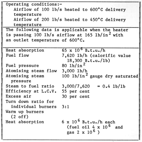
temperature has been reached. The heater performance data is given in Table 3.3.
|
|
Fig. 3.21 Cell 3 air heater
|
Table 3.3
Air Heater Performance Data
The air is routed from the heater to the Cell, as shown in Figure 3.17, by way of stainless steel
ducting. Air leaving the heater can be controlled over the range 300°C to 600°C as dictated by the test in progress
and final temperature control is obtained by mixing heated and unheated G.E.C. air in the mixing sphere.
3.5 Cell 3 Cold Air Plant
The cold air plant works in conjunction with a precooler and pressure dryer to reduce ice formation; temperatures down to
-70°C can be obtained by use of a cold air expansion turbine which is designed to give a maximum flow of 100 lb/s.
Temperatures between ambient and -70°C can be achieved by mixing warm air from the G.E.C. machines with that from the
cold air turbine in the air mixer which has special large valves to meter and blend the supplies.
When necessary, ambient temperature air can be drawn into the air mixer and blended with the cold supply; the circuits which
make this possible are shown in Figure 3.17.
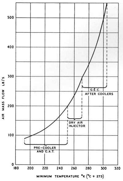
Figure 3.22 shows the temperature/air weight flow relationship obtained from the cold air plant and the
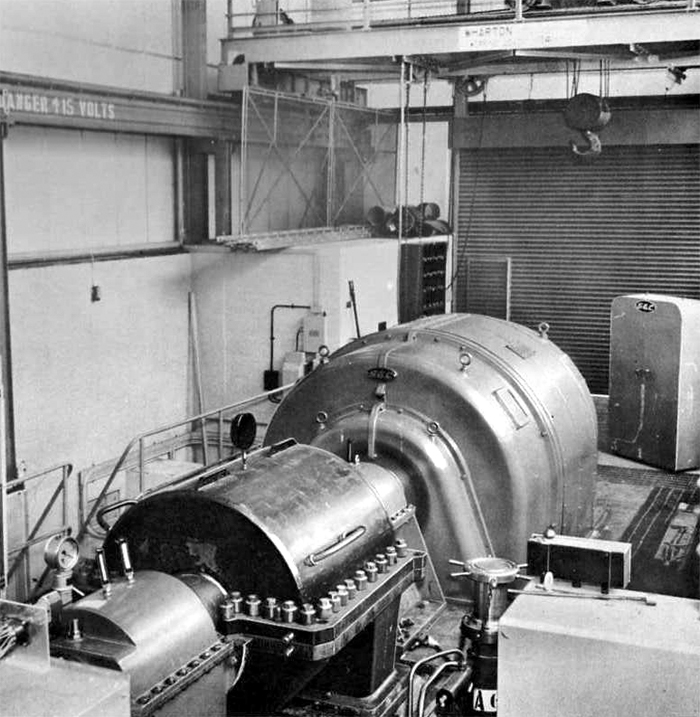
cold air expansion turbine alternator is illustrated in Figure 3.23. The power generated by the air expansion turbine is
absorbed by an alternator of five megawatt output and the electrical current is returned to the N.G.T.E.
grid supply.
|
|
Fig. 3.22 Cell 3 cold air plant temperature characteristics
|
|
|
Fig. 3.23 Cell 3 cold air turbine and alternator
|
3.6 Cell 3 Ice-making Facilities
Ice particles in air-breathing engine intakes can have a serious effect on performance. Consequently,
two special ice-making plants are installed in association with Cell 3
so that all altitude effects can be investigated. The two plants are:
- The ice crystal plant, and
- The super-cooled water droplet plant.
The former has the capacity to produce ice blocks which are cut into small particles and injected into the engine under test.
Ice blocks can be produced at teh rate of one ton every twenty-four hours and facilities exist for storing four to five tons
of ice for an indefinite period. The plant produces particles between 500 and 4,000 microns in size. The particle injection
rate is variable between 5.5 and 152 lb/min.
Alternatively, super-cooled water droplet plant can produce a spray of super-cooled water droplets within the
engine inlet duct. These will freeze out on contact with the cold engine inlet surfaces and so build up ice formations.
The basic air and distilled water system can deal with a water injection rate of up to 600 gal/h. A typical spray rake
can pass over 200 gal/h with a median droplet diameter of 20 micron.
3.7 Cell 3 Hot Fuel Supply
To simulate engine operating conditions at high speed in test plant at ground level it has become necessary
to preheat engine fuels to correspond with flight conditions where elevated fuel temperature occur when fuel is used
to cool the aircraft structure and services.
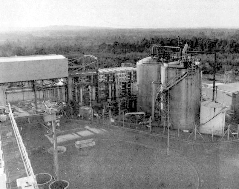
A plant, located near Cell 3, has been installed to
provide a service to heat fuel up to 250°C and pipelines have been laid to service Cell 3.
Mineral oil, heated in two oil fired heater units to temperatures up to 300°C, is passed through coils
in a 9,000 gallon capacity dwell tank to heat the engine fuel up to 100°C. The engine fuel is pumped from this dwell
tank to Cell 3 via heat exchangers in which the fuel is given a second stage
of heating by the mineral oil to raise the fuel temperature to the required level. The system supplies an engine under
test with up to 40,000 lb/h of fuel at temperatures up to 250°C and pressures up to 160 lb/in2. Higher
fuel flows up to 60,000 lb/h are possible but at correspondingly lower temperatures. A spill system, incorporating
a dump cooler, is used and transient flow conditions are possible with substantially steady inlet pressures.
The circuits used for fuel at temperatures above 100°C, including the heat exchangers, are
constructed from 18/8 stainless steel.
This system is also used with the heater units unfired to supply
Cell 3 with ambient temperature fuel.
3.8 Cell 3 West
Cell 3 West was constructed in 1969 at the West end of
Cell 3 suction manifold to provide the large diameter engine chamber required
for simulated flight altitude testing of fan engines such as the Rolls-Royce RB 211. The triple shaft design and high
by-pass ratio of these engines create a test demand which absorbs the whole of the present N.G.T.E.
exhauster resources, namely all eight G.E.C. and the Parsons
No. 9 and
No 10 machines. (See Figure 2.2).
Cell 3 West assists the commerical exploitation
of large fan engine design by enabling full flow cold air tests to be undertaken at flight operating
altitudes and under icing conditions. The performance of Cell 3 West
operating with the RB211 engine is shown in Figure 3.24 while Figure 3.25 shows a Rolls-Royce RB211
engine being installed.
|
|
Fig. 3.24 Cell 3 West typical test envelope with Rolls Royce RB211 engine
|
|
|
Fig. 3.25 Installing a Rolls-Royce RB211 engine in Cell 3 West
|
A cold air plant capable of cooling an air capactiy corresponding to the
maximum RB211 engine requirement has been built as part of the Cell 3 West
scheme. This cooler, described in paragraph 3.9 uses a 30% aqueous ammonia solution precooled to
-50°C in two cold stores which may be used separately or in series or in parallel operation. In
series operation one takn is brought on line to supply the air cooler, followed by the second tank when
the "cold" in the first tank has been expended. In parallel operation both tanks are on line together
to supply the air cooler. At maximum design conditions there is sufficient "cold" stored to permit the
RB211 engine to run for up to 60 minutes but with less arduous air flow and temperature demands the
test duration can be proportionately longer. The engine chamber can be run both with and without
cold air; in the latter case air is drawn either direct from atmosphere through an intake silencer
or through the cooler with no coolant circulation. In all cases the engine is directly coupled to
the intake so that all engine tests are of the connected type.
The large diameter engine chambre has also been used extensively to accommodate
simulated wet icing testing of full scale helicopter rotors. The Rolls-Royce Olympus 593 engine with
a Concorde intake has been tested under simulated wet icing conditions. All tests were conducted in
the free jet mode.
Provision has been made on the engine chamber for a pressure connection from the
G.E.C. machines in order than the chamber can be converted to a blown test bed if required.
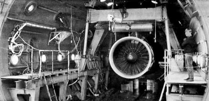
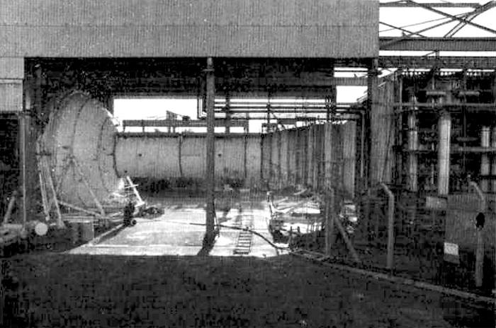
Figure 3.26 shows a general view of Cell 3 West
whilst Figure 3.27 shows the front of the Cell with the end dome and inlet ducting removed to expose
the inside compartment and a RB211 engine installation. The removal of the end dome permits easy
access for installation of the engine.
|
|
Fig. 3.26 General view of Cell 3 West
|
|
|
Fig. 3.27 View of Cell 3 West engine chamber with the front dome removed
|
Figure 3.28 shows the cell end dome in the testing position with the inlet duct connected to the inlet
control valve and air cooler. The Cell 3 West engine chamber is 25 ft diameter
and 40 ft long and an extension of the Cell 3 exhaust manifold, which is
15 ft diameter, is directly coupled to the exhaust end of the cell. Cell 3 West
has been built at ground level unlike Cell 3 and consequently the exhaust
manifold passes through two cascaded right angle bends in order to accommodate the height difference. The
Cell 3 West exhaust manifold is fitted with bulkhead doors which are shut
in non-testing periods when the suction mains may be in use for Cell 3 and
Cell 4. The atmospheric to exhaust mainfold pressure difference helps to
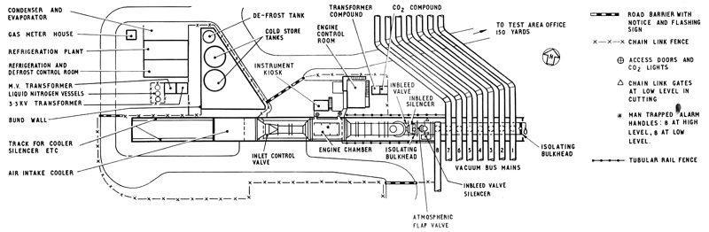
keep a pressure tight seal. Figure 3.29 shows the arrangement of the engine chamber relative to the eight G.E.C. suction mains
and it should be noted that a similar isolating bulkhead is located on the Cell 3
end of the manifold so that installation and modification work can proceed in Cell 3
whilst Cell 3 West is operational.
|
|
Fig. 3.28 View of Cell 3 West engine chamber with the front dome in the testing position
|
|
|
Fig. 3.29 Cell 3 West Test Area
|
To maximise exhauster performance, an internal exhaust gas diffuser is sited in the parallel
section of the exhaust duct immediately downstream of the engine exhaust nozzle. The vertical exhaust duct from
Cell 3 West which joins the exhaust manifold is fitted with direct
injection water cooling sprays and an inbleed valve for altitude trimming purposes. A further inbleed valve
is fitted in the exhaust manifold downstream of the isolating bulkhead.
It is possible to measure engine thrust in Cell 3 West
as the engine mounting includes special features to permit the movements required for thrust and drag measurements.
The engine is clamped to a support frame which is itself supported from flexible rods attached to the roof of
the cell. The mounting permits the small deflections which are needed to measure thrust and draft on
Davey United Ltd. load cells*. The engine installation includes an automatic-connect bulkhead arrangement
so that a large proportion of engine instrumentation and other service supplies to the engine are automatically
made when the engine is lifted into its finally installed position. This arrangement is identical to sea
level installations at Rolls-Royce, so that it is possible to make speedy interchange of engines between sea
level and altitude test facilities.
* The thrust measuring system will be changed in 1982 to an improved arrangement, using
Bofors shear force load cells.
The inlet ducting which connects with the cooler is 77 ft long, of which 43.5 ft is external
to the cell and the rest internal. This ducting includes an air flow measuring section as well as air
straightening gauzes which improve the air distribution at the engine entry plane. A louvre type air inlet control
valve is fitted between the air cooler and the cell external ducting.
Both steady state and transient instrumentation is available and test information is normally
fed through the on-line ICL1904S* computer. Although the instrument installation is able to provide 700 pressures
and 800 temperature channels for steady state conditions although only 1000 can be addressed at one test point.
Thirty-six channels of U.V. and 32 channels of magnetic tape are available for transient conditions. A control
room adjacent to the cell is used to operate the test plant, the engine and its associated auxiliaries. Further
details of the instrumentation services is given in Section 4.
The fuel system is tapped off from that used in
Cell 3 and is of similar design. A spill return line is situated close
to the engine supply tee-off and fuel in excess of that required by the engine is returned to the plant
fuel supply tank. This arrangement eliminates the need to accelerate large quantities of fuel through
the long supply pipework during engine transients.
The spray cooling water system operates on a recirculatory basis with a make up supply
to replace water evaporated into the air stream. Two banks of spray nozzles are provided and each is fitted
with on-off and flow control valves. The quantity of water injected is carefully controlled to ensure than just enouhg
is sprayed into the gas stream to maintain an acceptable gas temperature at inlet to the exhausters.
3.9 Cell 3 Cold Air Plant
The air intake cooler consists of 33 modules built in three rows of eleven modules. Each module
has 18,500 ft run of 1 in o.d. x 16 B.G. mild steel pipe of plain section. The tubes are galvanised externally
and the module headers are interconnected toegether in such a way as would allow the cooler modules to be removed
for emergency repairs. Altogether, when all modules are interconnected, the cooler has a total length of
61 ft 5 in with frontal dimensions of 27 ft x 29 ft 6in. The assembly is mounted on its own wheeled carriage and
the cooler can be wheeled out of position along its own track if required. Figure 3.26 shows the air cooler in front
of the cell, the two cold storage tanks, the smaller defrost tank and the refrigeration plant. The cold storage tanks
are nominally 43 ft high x 25 ft diameter.
|
|
Fig. 3.30 View of Cell 3 West cooler assembly
|
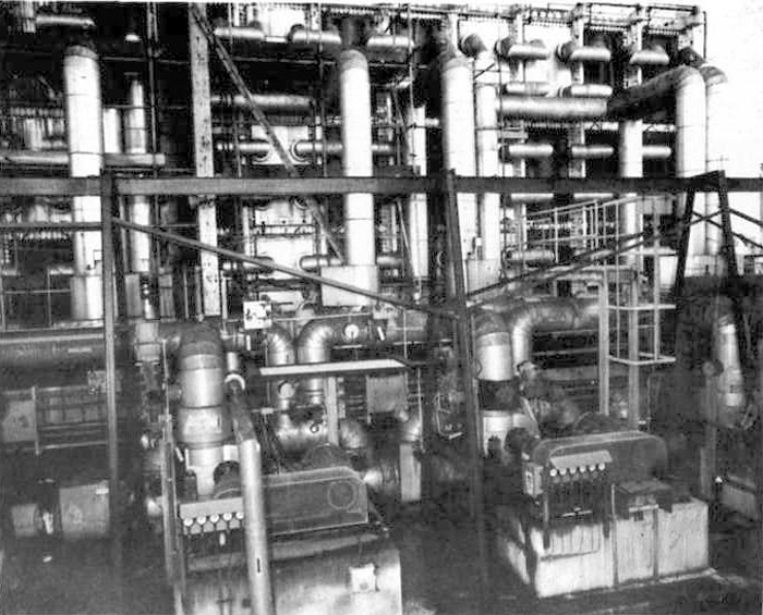
Each 500 tonne cold store of aqueious ammonia can be reactivated in twenty-four hours using the
refrigeration plant which is sited adjacent to the cold store tanks. This refrigeration plant includes the necessary
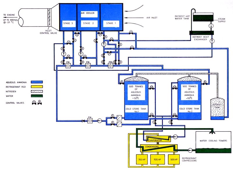
condensers, evaporators, pumps, etc., and is of conventional design rated at 2.25 million B.t.u./h. A simplified
diagram of the cold air system is shown in Figure 3.32
|
|
Fig. 3.32 Diagram of Cell 3 West cold air system
|
Coolant from the pre-cooled store of aqueous ammonia is circulated through the cooler which is divided into
three stages for this purpose. Each stage of the cooler has an independent flow control system and coolant is recirculated wherever
possible to ensure maximum use of the "cold". Eventually the coolant is returned to the cold store where an interface, formed between
the "warm" and "cold" coolant, travels down the tank as testing proceeds. The duration of a run is dependent on the
rate at which coolant is drawn from the tank(s) and the position of the interface. Under some circumstances the length of test
run may be limited by the falling off in heat transfer coefficient due to ice building up on the outside of the cooler tubes.
The second cold store tank was installed in 1980. This tank has been designed to be used independently, or in series or
parallel operation with the original tank.
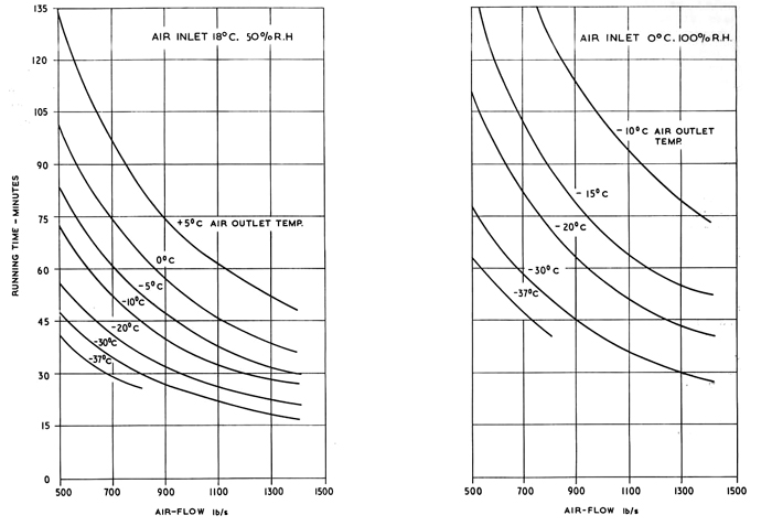
The cooler has been designed to give thirty minutes running time at -37°C with an air
throughput of 800 lb/s assuming air inlet conditions of 7.3°C dry bulb temperature and 100% relative
humidity using one storage tank. The estimated performance of the cooler using one cold store tank at
various air inlet conditions is shown in Figure 3.31. When using two cold store tanks in series or parallel operation
the running time will be limited by pressure losses through the air cooler due to ice formation on the tubes.
The rate of ice formation will be determined by the atmospheric temperature and humidity conditions
prevailing at the time of the test. Optimum cooler performance is achieved by use of a computer program
which predicts the cooler performance over a wide range of operating conditions.
|
|
Fig. 3.31 Cell 3 West estimated performance of air inlet cooler using one cold store tank
|
3.10 Cell 3 West Wet and Dry Ice Facilities
Wet icing conditions may be simulated in Cell 3 West
by injecting supercooled de-mineralised water spray droplets into the low temperature airstream
entering the engine. The droplets remain in the liquid state until striking a solid surface, whereupon
they freeze. The resulting ice build-up is recorded photographically and by means of closed circuit
television monitors, with video tape-recording facilities. Stroboscopic lighting allows the
ice formation on rotating blades to be studied.
The de-mineralised water is injected through 242 spray nozzles fitted in a 93
inch diameter spray rake located in the engine approach ductwork. The spray nozzles are of an air blast
atomisation type, manufactured to a Rolls-Royce design, with interchangeable water jets. The atomisation air
is heated by a stream heat exchanger and the air temperature is regulated to a minimum temperature of
approximately 5&dec;C at the spray nozzle exit, to prevent freezing of the nozzles and water droplets.
The water droplet size (volumetric mean diameter) is variable between 20 and 40 micron.
A dry ice facility is available to supplement the wet icing system. The dry ice equipment
cuts pre-formed conditioned ice blocks into small crystal particles and injects these particles into the
engine inlet airflow from a station in the cell external ductwork, downstream of the air cooler. The
mean particle size range is from 500 micron to 2,000 micron with an injection rate of 30 lb/min to
125 lb/min, based on a mean particle size of 1000 micron. Mixed icing conditions may be simulated by
combined operation of the wet and dry icing facilities.
In addition to engine testing in the nromal connected mode, with or without icing
facilities, Cell 3 West has also the capacity to be used as a free
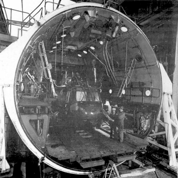
jet facility for simulated icing tests. Figure 3.33 shows a Sea King helicopter fuselage being installed in
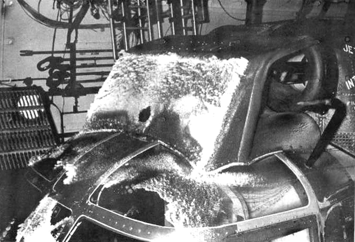
Cell 3 West in preparation for icing tests whilst Figure 3.34 shows
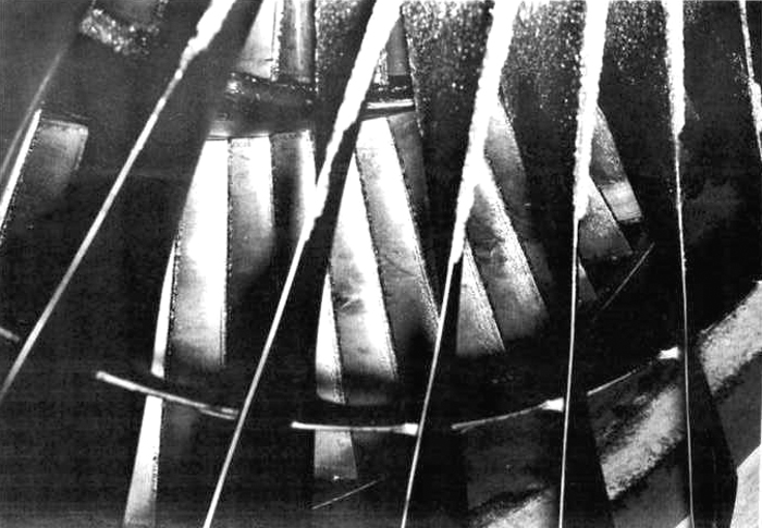
the resulting build-up of ice in the region of the engine air intakes. Figure 3.35 shows the ice formation on
the fan blades of a Rolls-Royce RB211 engine during a wet icing test.
|
|
Fig. 3.33 Sea King installation in Cell 3 West
|
|
|
Fig. 3.34 Sea King icing test in Cell 3 West
|
|
|
Fig. 3.35 Ice-accretion on the fan blades of a Rolls-Royce RB211 engine
|
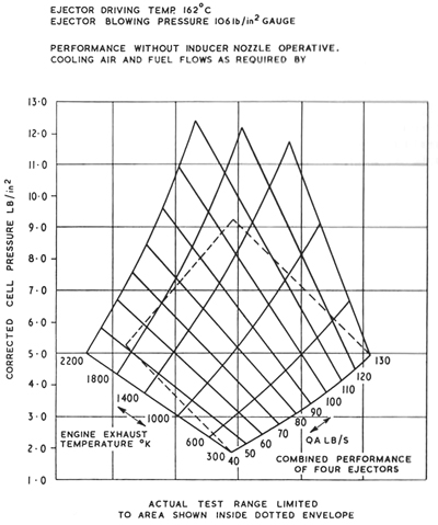
3.11 Cell 4 Test Plant
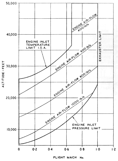
When gas turbine engines are chosen to operate in supersonic aircraft, there is a need to test the engine
in close association with the aircraft air intake system which is designed to reduce the air speed at the
compressor face to an acceptance velocity thus converting the forward ram velocity into high engine
intake pressure with a resultant bonus in power plant performance.
Although the engine an intake problems arising in supersonic flight are inter-related, a true
simulation of all relevant factors is only achieved if full-scale free jets are possible;
Cell 4 provides this capability for engines such as the Rolls-Royce
Olympus 593 engine for Concorde and it is possible to test this engine and similar power plants with their intakes
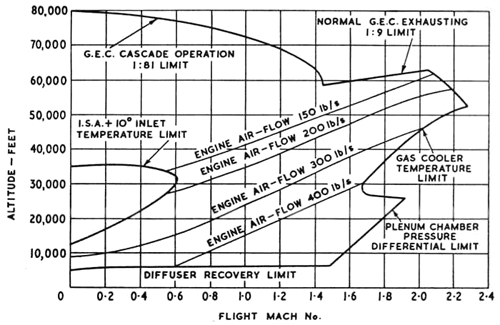
and control systems under high speed flight conditions. The Cell provides a means of observing on the ground the
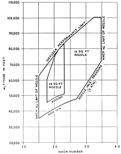
interaction of the intake and engine at changing altitude, Mach number and incidence. The performance range of
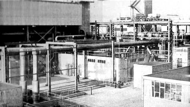
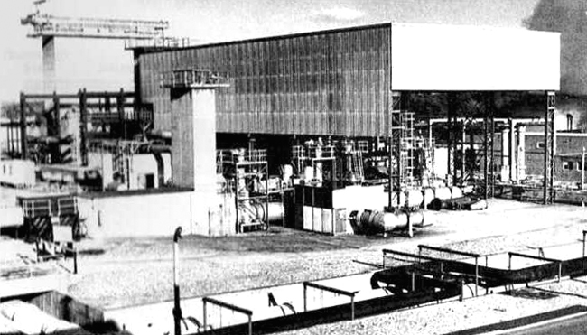
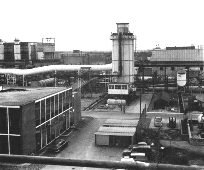
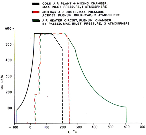
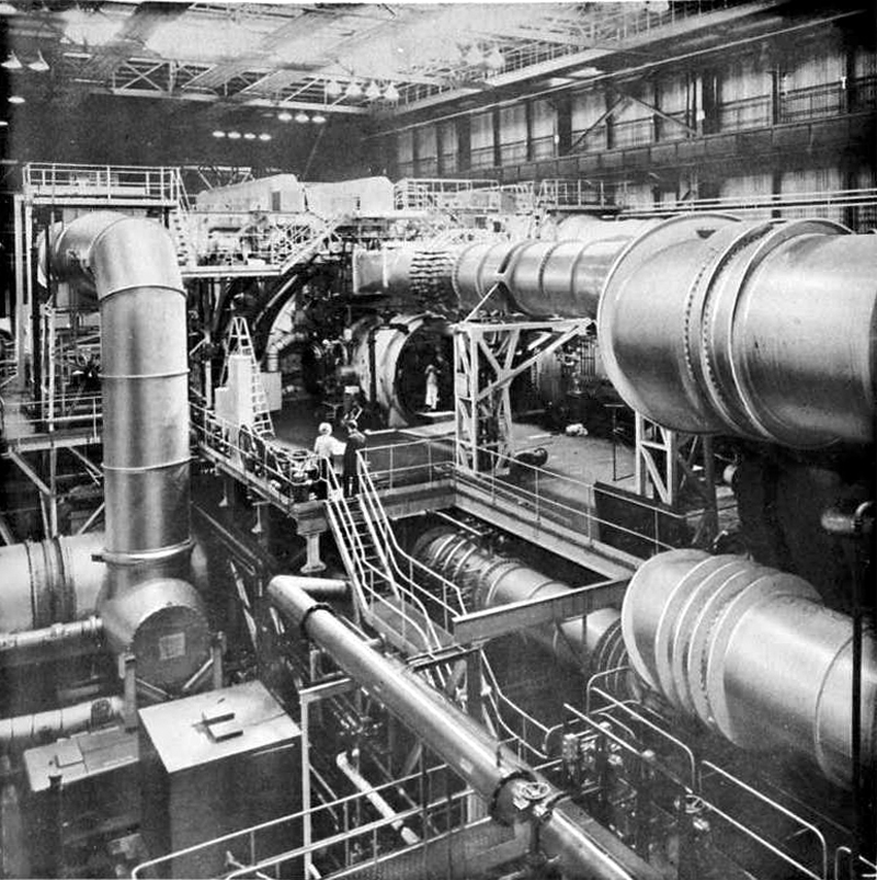
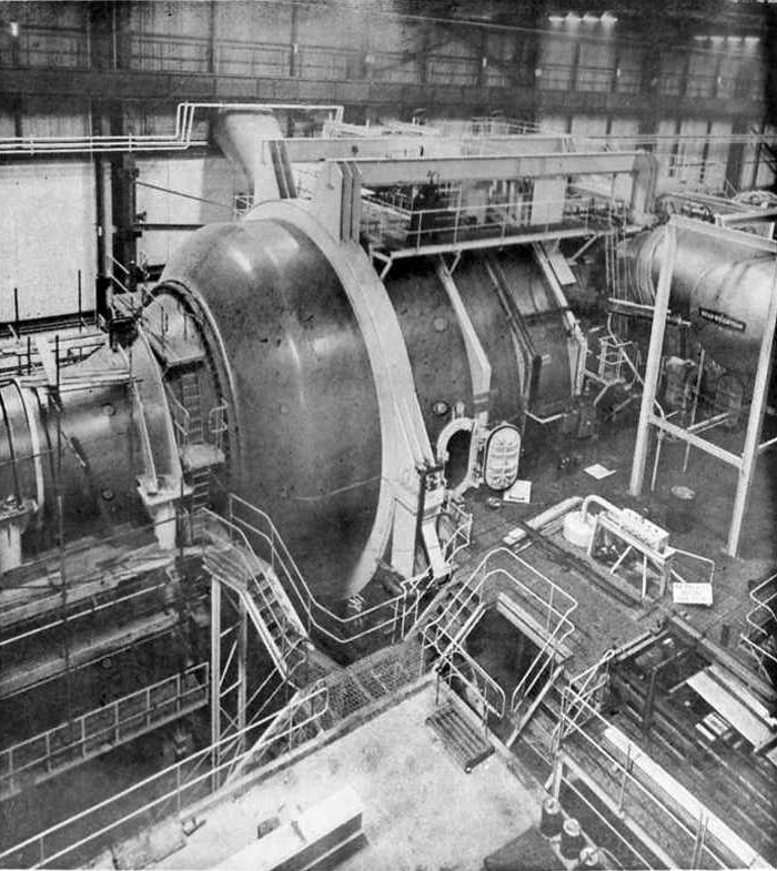
Cell 4 is given in Figure 3.36. Figures 3.37 and 3.38 show
actual views of the Cell 4 plant and associated machinery and
some idea is obtained of the size and engineering complexity of full-scale free jet tests. In addition to
testing in the free jet supersonic mode, the cell has also been used for subsonic free jet testing of the engine
and intake. Also, by removing the blowing nozzle, connected testing of engines with reheat has been successfully
undertaken with an experimental thrust measurement system installed in the engine mounting frame.
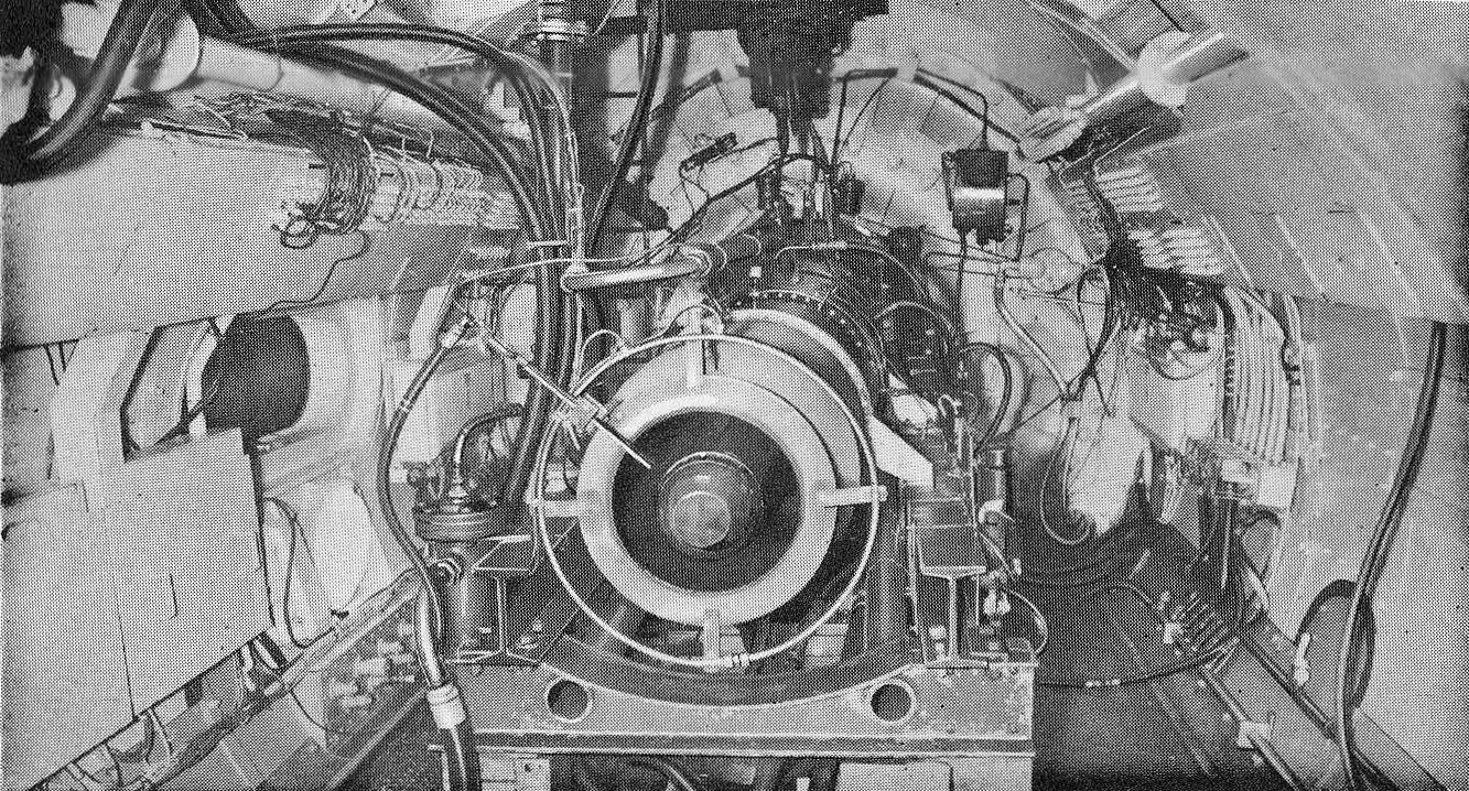
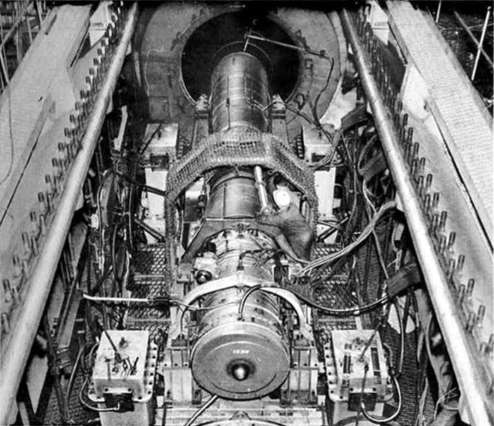
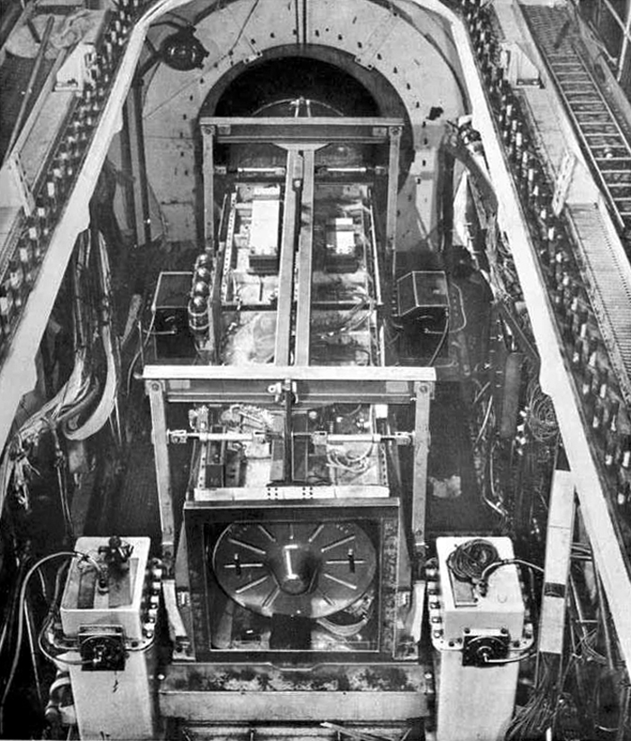
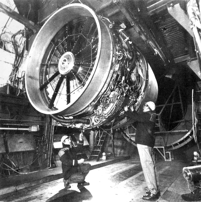
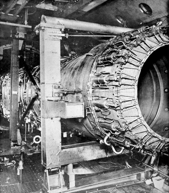
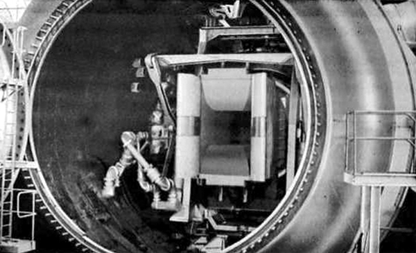
Figure 3.39 shows the Rolls-Royce Olympus 593 engine installed in the Cell 4
engine chamber; this view is taken from the engine tailpipe end with the propelling nozzle in the immediate
foreground, looking forward to the bulkhead which divides the engine chamber from teh intake
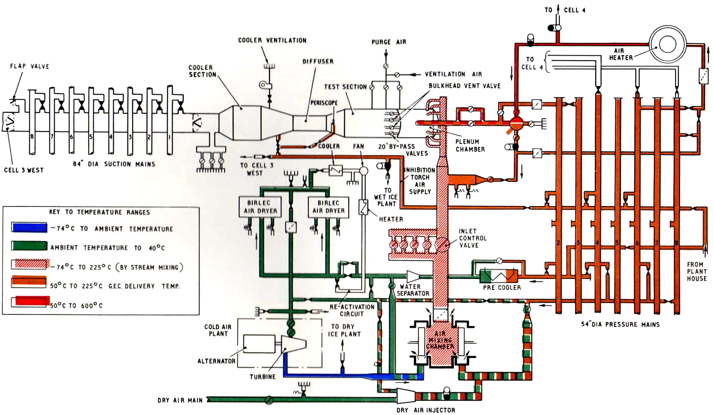
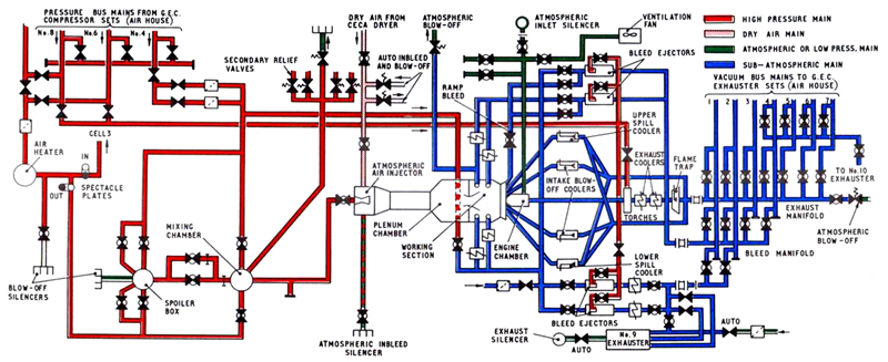
working section. Figure 3.40 shows the air circuit diagram for Cell 4
which is designed to handle a maximum flow equivalent to two G.E.C. sets, i.e. 400 lb/s, under pressure
conditions, with the capability of increasing this flow to 600 lb/s at lower pressures by the use of
an injector system.
|
|
Fig. 3.36 Performance envelope for Cell 4 plant
|
|
|
Fig. 3.37 General view of Cell 4
|
|
|
Fig. 3.38 Cell 4 plenum chamber
|
|
|
Fig. 3.39 Rolls-Royce Olympus 593 for Concorde installed in Cell 4 engine capsule
|
|
|
Fig. 3.40 Cell 4 process air diagram
|
The total air mass flow can be provided as dry air from the
Ceca air dryer which is described in para 2.8. Normally, the
Cell air supply maximum inlet pressure does not exceed three atmospheres absolute and the temperature ranges
from 70°C to 470°C using the air heater described in para 3.4. The Cell is built parallel to
Cell 3; the relative position of these plants is shown in
Figure 2.3 which also shows the inter-connecting ducting with the G.E.C. and
No. 9 and
No. 10 exhausters.
Flight speed is simulated by a supersonic blowing nozzle which has an adjustable throat and
wall contour to provide variable Mach number operation. This nozzle is mounted on a universal carriage which enables
aircraft pitch and yaw conditions to be simulated up to angles of +/- 10° at rates of up to 20° and
10° per second respectively. The total weight of the nozzle and moving carriage assembly is approximately
75 tons. Figure 3.41 shows the carriage assembly with the 25 square foot nozzle in position viewed through the plenum
chamber with the 20 foot diameter inlet cone removed.
|
|
Fig. 3.41 Cell 4 carriage assembly and supersonic blowing nozzle
|
To match engine performance more closely two variable nozzles are
available; the first is 12 sq ft in area, giving a Mach number ange of 1.5 to 3.5 while the second
is 25 sq ft in area giving a Mach number range of 1.7 to 2.5.
For subsonic testing the variable supersonic blowing nozzle is replaced by a
non-variable sheet steel blowing nozzle which is designed to meet the requirement of the particular
cell installation.
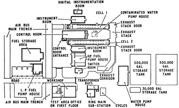
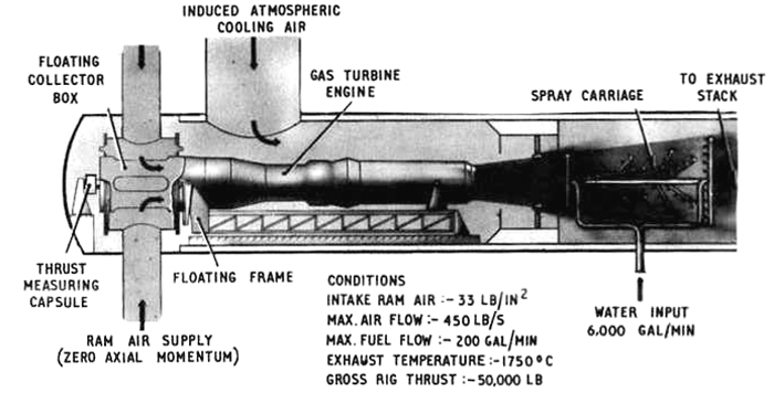
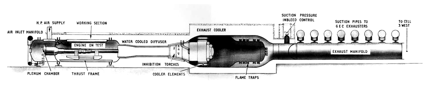
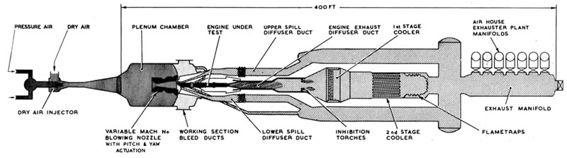
A general cross sectional view of Cell 4
is shown in Figure 3.42. The diagram illustrates how the aircraft intake is mounted in the working
section immediately downstream of the blowing nozzle with the engine coupled behind.
|
|
Fig. 3.42 Cross section of Cell 4 altitude test plant
|
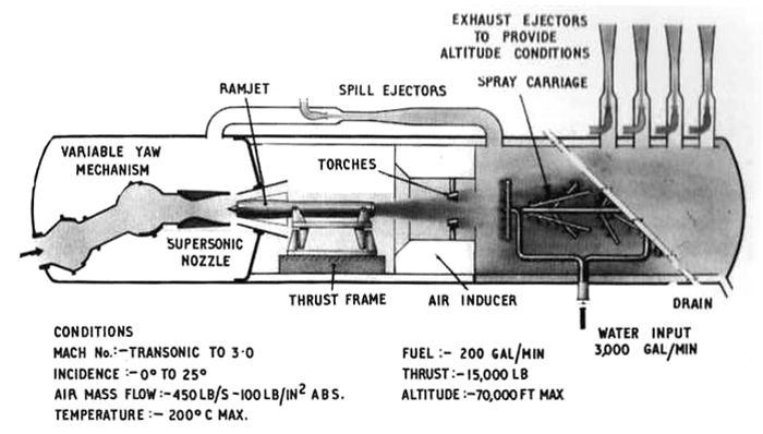
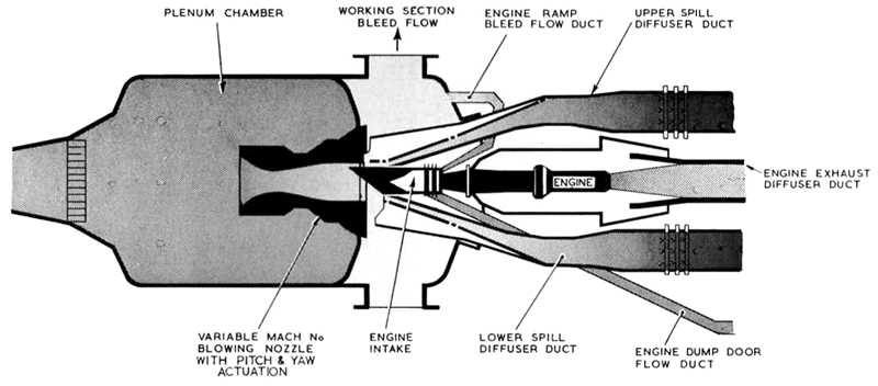
Spill diffusers, which are shown more clearly in Figure 3.43, are mounted above and
below the intake and are used to obtain altitude conditions in the working section by converting low
pressure, high velocity air from the nozzle into higher pressure, low velocity air. As the downstream end of
the spill diffusers are connected to exhausters it can be seen that the diffusers are a means of aiding
the exhausters to obtain altitude. Changes in altitude are obtained by varying the geometry of the
diffuser.
Better use of the installed exhauster capacity is obtained by sucking away
the low energy air issuing from the supersonic blowing nozzle, normally about four per cent
of the nozzle mass flow. This process is termed "working section bleed" and is performed by the
No. 9 machine referred to in para 2.3.
Figure 3.43 shows diagrammatically the flow paths in the supersonic nozzle,
spill diffuser and engine intake. The geometry of the Concorde intake makes it necessary to provide
additional ductwork to accommodate the "ramp bleed" and "dump door" flows which are an
essential feature of the Concorde aircraft power plant. The ramp bleed flow is piped away from
the upper part of the intake and returned to the working section to be sucked away by
No. 9 exhauster machine. The dump door flow is sucked
away through one of the two permanent plant blow-off ducts to join the main exhaust system
further downstream.
|
|
Fig. 3.43 Cross section of Cell 4 intake assembly, and flow ducts for
Rolls-Royce Olympus 593
|
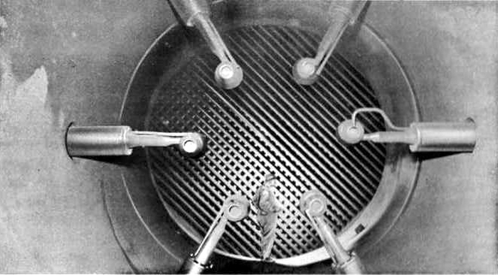
As in all altitude cells, the heat exchanger needed to cool the engine exhaust
is a major plant item. The Cell 4 gas cooler has two
stages, the first stage cooler is shown pictorially in Figure 3.44 which also shows the six
flame torches that ignite any unburnt fuel in the engine exhaust so that explosion risks are
eliminated. The exhaust gases leave the water-cooled diffuser duct at temperatures up to
1,700°C to enter the first stage cooler where they are cooled to 1,000°C by a novel
gasover-tube matrix; a water flow of 620,000 gal/h is circulated through the matrix. In the second
stage cooler, where the gases pass through the tubes in a conventional manner, the temperature
of the gases is reduced to 150°C. This second stage also has a water circulation of 620,000
gal/h. Additionally, the flow from direct injection water sprays is used as evaporative cooling
to reduce the gas temperature further to 50°C, this latter temperature being the maximum for
the inlet flow to the G.E.C. exahusters. The excess water from all the direct injection sprays
drains from the air ductwork into a 40 ft deep barometric well. The well is divided into two sections.
Clean water is drained into one section from which it is pumped back to the water storage ponds, and
water that has been contaminated by the exhaust gases is drained into the second section from which it
is pumped into the site sooty water plant described in Section 5. The total
recirculating flow of all cooling water systems in Cell 4 under
hot running conditions is 2.5x10⁶ gal/h. Losses up to 170,000 gal/h through evaporations,
leakages and contamination are incurred.
|
|
Fig. 3.44 Cell 4 first stage gas cooler matrix
|
The exhaust cooling system is manufactured entirely from conventional ferrous materials.
During non-running periods corrosion is arrested by filling the system with a solution of sodium suplhite and
sodium hydroxide.
Altogether, Cell 4 has a total length of
approximately 400 ft of which the 30 ft diameter inlet plenum chamber with its blowing nozzle contributes
36 ft and the working section 10.5 ft. The engine chamber itself has a diameter of 10 ft and a length of
16 ft and the exhaust diffuser 55 ft; the first and second stage coolers have diameters of 26 ft and 18 ft
respectively, the total length of the two stages is 160 ft, whilst 105 ft of ducting at the rear end
of the cell accommodates the seven G.E.C. exhauser connections.
The fuel system is teed off that serving Cell 3
and described in para 3.3. As both cells do not run at the same time, no inconvenience is suffered by
having a common system. The fuel flow rates are 100 gal/min and 200 gal/min for engine and reheat systems
respectively. Normally, the engine flight fuel pump is used on engines installed in
Cell 4, therefore, the plant fuel system provides fuel to the
engine low pressure pump at a set pressure of 25 lb/in2; however, if needed, fuel at pressures
up to 100 lb/in2 can be supplied.
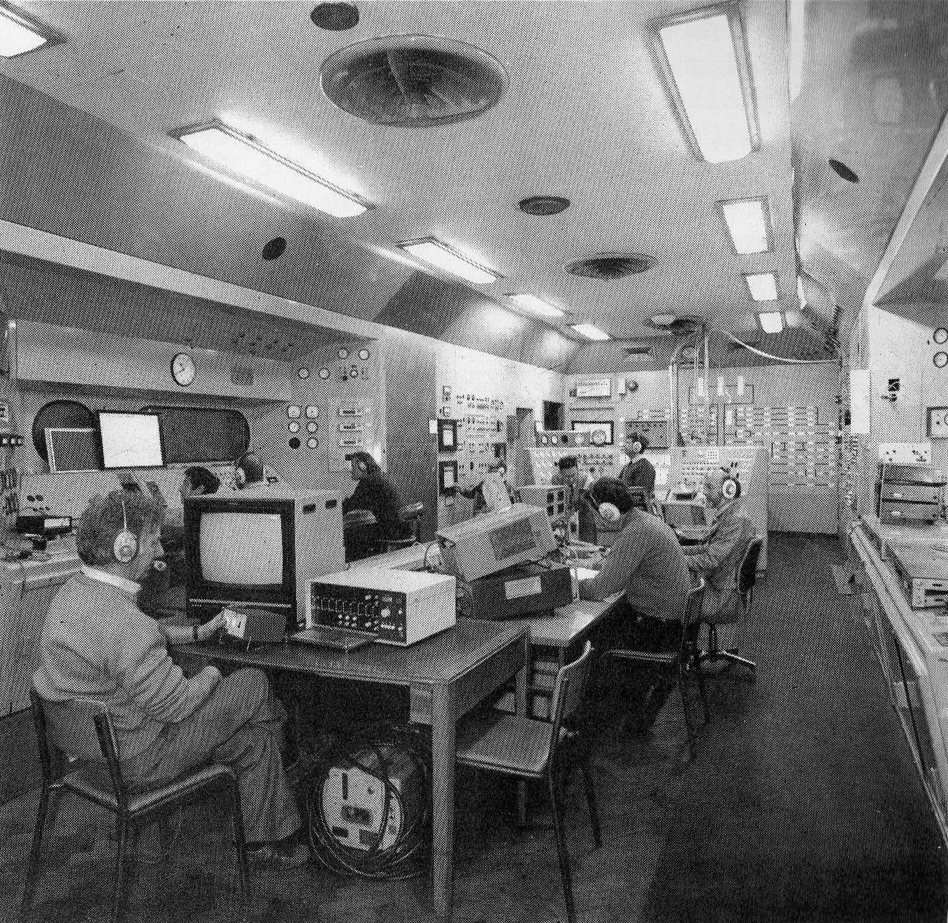
|
|
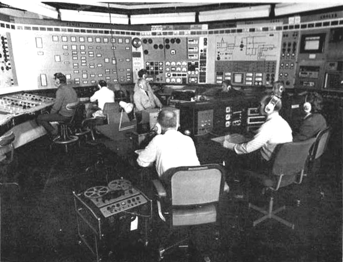
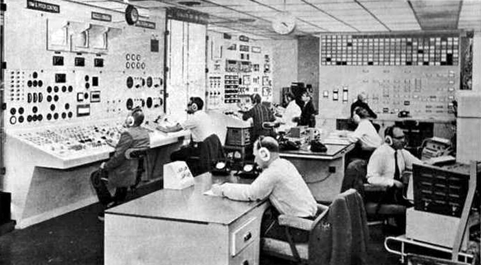
Fig. 3.45 Cell 4 control room with test in progress
|
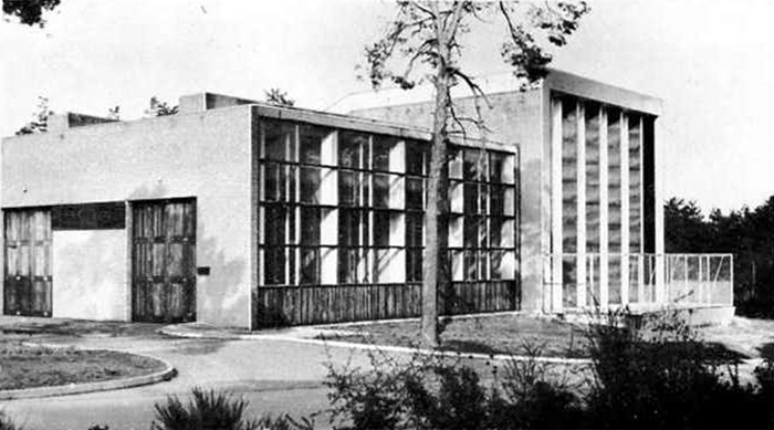
3.112 Sea-Level Engine Testing Plant (The Glen Test House)
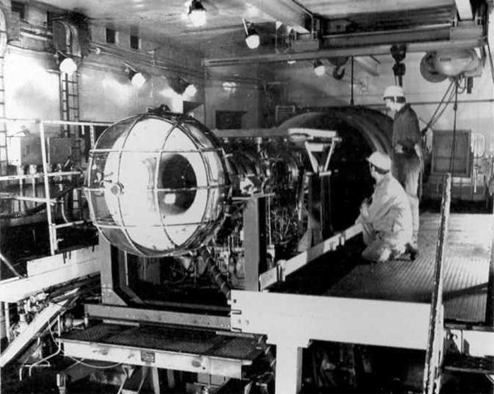
The facilities required for testing gas turbine engines under sea-level
conditions are not so complicated as those needed for simulated altitude flight conditions which
have already been described; however, userful and much less expensive development work can
be conducted on sea-level static beds. Figures 3.46 and 3.47 show views of the New Site sea-level
test bed which is known as the Glen Test House (Ground Level Engine Test House).
|
|
Fig. 3.46 External view of the 'Glen' test house
|
|
|
Fig. 3.47 Aircraft gas turbine installed in the 'Glen' test bed
|
The test bed was originally designed for engines of up to 28,000 lbf of thrust,
but shear force load cells are now installed permitting thrusts of up to 44,000 lbf to be measured.
Inleft air to the test bed is drawn through intake acoustic splitters which are designed to handle
1000 lb/s. Exhaust gases from the engine under test together with induced air are vented to atmosphere
through a detuner. The detuner is fitted with water spray cooling, the water being supplied at a maximum
flowrate of 42,000 gal/h at 60 lb/in2.
There are various fuel systems supplied to the test bed and fuel can be drawn from
either the Tank Farm or from a bowser located at the Glen Test House. The normal low pressure fuel system
is capable of supplying 2000 gal/h at 25 lb/in2, the reheat low pressure system can supply
21,900 gal/h at 35 lb/in2 and the reheat high pressure system can supply 10,000 gal/h at 1200
lb/in2.
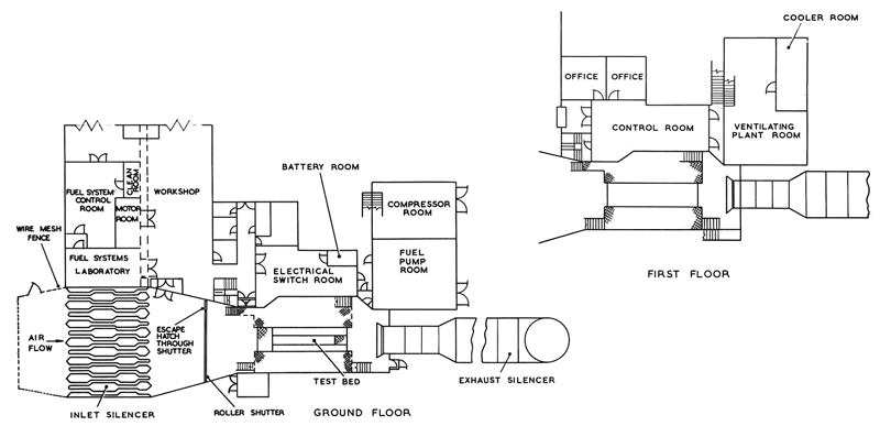
Figure 3.48 shows a plan view of the Glen Test House and it will be noted that it includes
a Fuel System Test Facility (FSTF). This facility consists of a laboratory and motor room housing a 225 h.p.
variable speed electric motor coupled to a two-stage gearbox set and also a low pressure fuel supply system.
The motor gearbox set is capable of driving a wide range of engine fuel pumps at speeds up to 50,000
rev/min. In addition to the above, the facility also comprises a control room and a clean room for the
stripping/servicing of hydraulic and fuel system components. The basic purpose of the FSTF is to allow
testing to be carried out on engine fuel pumps and fuel systems in isolation from the engine itself.
|
|
Fig. 3.48 Plan layout of the 'Glen' test house
|
© Procurement Executive, Ministry Of Defence