The Buildings
home | the buildings | cell 3 west (649)
Cell 3 West (649)
Built: 1969
Decommissioned: 2002
Cell 3 West was the last altitude test cell to be built at Pyestock in 1969. Its construction was
prompted by the need to test a new breed of large civil turbofan engines, such as the Rolls-Royce RB207
and RB211, over their full flight envelopes.
The existing infrastructure for the new testing facility was mostly in place and so the new cell was
plumbed into the existing suction manifold at the end of Cell 3.
New exhauster capacity was also required
as the demands of these engines (with their triple-shaft designs and high-bypass ratios) absorbed all the
existing exhauster resources at Pyestock. So
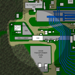
Number 10 Exhauster was built to the north of the cell and a
cold air plant was constructed to its west. Even though it was mainly a capability enhancement to
Cell 3,
Cell 3 West was a test cell in its own right.
|
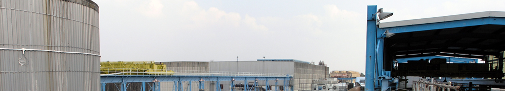
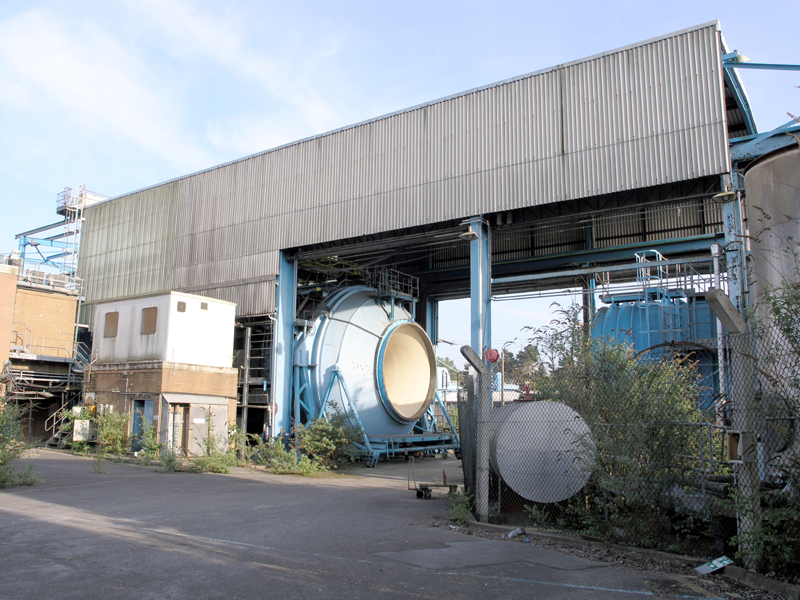
A view of Cell 3 West whilst walking southward down
G Road.
05|05|07 © Simon Cornwell 2007
|
The engine chamber was constructed above ground and had the largest diameter of any of the altitude test cells at
Pyestock. It had a 25ft. diameter and was 40ft. long (with a 30ft. long working section). The cell was built at
ground level and so the exhaust manifold passed through two cascaded right angle bends in order to accommodate
the height difference to the entrenched suction manifold. The exhaust manifold was fitted with bulkhead doors
which were shut during non-testing periods. The atmospheric to exhaust manifold pressure difference helped to
keep the pressure tight seal.
The front dome of the cell and inlet ducting could be removed to expose the inside compartment. This allowed
easy access to the engine at the time of installation. The inlet ducting was 77 ft. long of which 43.5ft was
external to the cell.
Initially the engines under test were directly coupled to the intake so all tests were of the connected type.
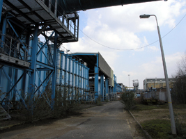
|
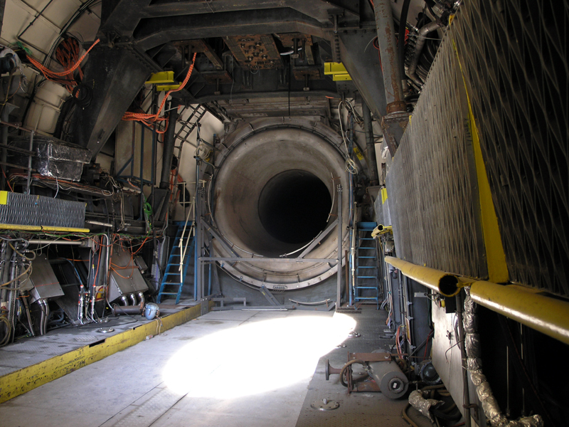
Looking north-east across the Engine Chamber of Cell 3 West.
05|05|07 © Simon Cornwell 2007
|
The engine chamber could be run with or without cold air. The air could be drawn direct from
atmosphere through an intake silencer or through the newly build cold air plant. This plant
used 30% aqueous ammonia solution pre-cooled to -50°C in a cold store which could supply enough
cold air to permit the RB211 engine to run for approximately 30 minutes at full flow. The air
temperature could be reduced to -40°C in the cell which was equivalent to a civil aircraft cruising
at an altitude of 40,000 feet. Either water (wet icing) or ice particles (dry icing) or a combination
of both could be injected into the cooled inlet air stream.
It was possible to measure engine thrust as the engine mounting included special features to permit the
movements required for thrust and drag measurements. The engine was clamped to a support frame which
was itself supported from flexible rods attached to the roof of the cell. The mounting permitted small
deflections which were used to measure the thrust. The engine installation also included an automatic-connect
bulkhead featuring a large proportion of engine instrumentation and other services
which were identical to the sea-level installations at Rolls-Royce, so the speedy interchange
of engines was possible.
|
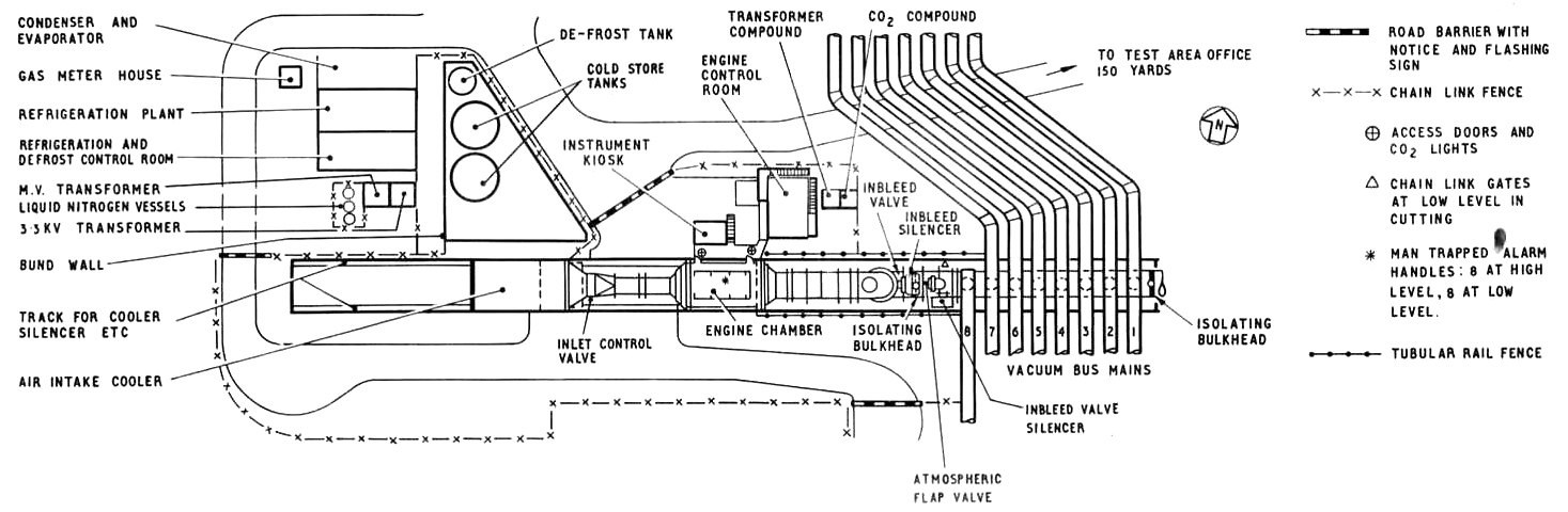
|
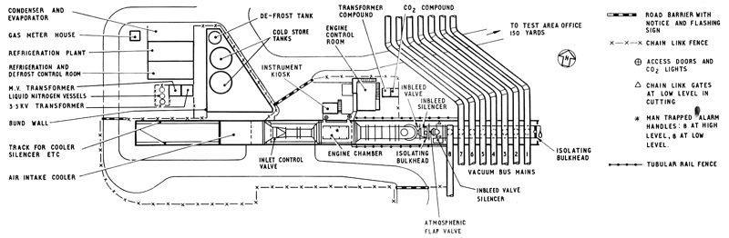
Cell 3 West Test Area
|
Both steady-state and transient instrumentation were available. Test information was fed through to
the SDS 9300 computer in the Computer Building
with the PDP7 data acquisition unit in support.
300 pressures and 200 temperature points for steady state conditions and 30 channels of UV and 28
channels of magnetic tape of transient conditions were available. (The later installation of the
ICL 1904S computer allowed 700 pressures and 800 temperature channels to be used along with 36 channels
of UV and 32 channels of magnetic tape). A control room adjacent to the cell was used to operate the test
plant, the engine and its associated auxiliaries.
The fuel system was tapped off Cell 3 and was of similar design. The spray cooling water system operated
on a circulatory basis. Two banks of nozzles were provided and each was fitted with on-off and
flow-control valves. The quantity of water injected was carefully controlled to ensure that just
enough was sprayed into the gas stream to maintain an acceptable gas temperature at inlet to the exhausters.
|
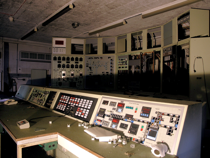
Cell 3 West control room looking north-east.
24|03|07 © Simon Cornwell 2007
|
During its lifetime, the cell was readily adapted for new tests under differing conditions. It was converted
to allow free jet testing so that full-flow cold air tests could be undertaken at flight operating altitudes.
The cold-air plant was expanded with extra tanks to further decrease the temperature range or allow tests
to run for longer. With these modifications, the simulated wet-icing testing of full-scale helicopter rotor
blades, as well as the Rolls-Royce Olympus 593 with Concorde intake,
could be tested under simulated wet icing conditions.
In its final years, the cell was used for icing certification tests to CAA and FAA regulations. These could be
conducted by the installation of a spray rake that provided an icing cloud of controlled Light Water Concentration
and droplet size. In addition to full engines, air frame components could be tested and helicopter de-icing carried out.
The cell was also being considered for sea-level testing but it�s unknown whether this modification was ever carried out.
Cell 3 West was closed in 2002 when the rest of its support network (the
Air House and
Cell 3) were also closed.
Cell 3 West Walkthrough...
Further Reading
|