|
National Gas Turbine Establishment
home | documentation | literature | the aeronautical activities of the national gas turbine establishment
The Aeronautical Activities Of The National Gas Turbine Establishment
(A Lecture by D/NGTE to the Manchester Branch of the R.Ae.S on 12th Dec. 1973)
THE AERONAUTICAL ACTIVITIES OF
THE NATIONAL GAS TURBINE ESTABLISHMENT
The modus operandi of the National Gas Turbine Establishment still reflects
its growth from two widely diverse roots, one in government research and the
other in industry. The Establishment originated in 1944 from a merger of the
Gas Turbine Division of the RAE with the original UK jet engine company
founded by Sir Frank Whittle, i.e. Power Jets Ltd. The combination first ran
as a company, Power Jets (R&D) Ltd, but in 1946 the latter was hived off as
an exploitation organisation and the main body reconstituted as the National
Gas Turbine Establishment under the Ministry of Supply.
FUNCTIONS
Notwithstanding that it is the premier heat engines laboratory in the UK and
the only one that maintains an interest in all aspects of the gas turbine
engine on land, at sea and in the air, NGTE is primarily an aircraft
propulsion laboratory. Administratively, it is incorporated in the Procurement
Executive of the Ministry of Defence and functions on a customer/contractor
basis . Of its research programme one half deals with the gas turbine engine
per se and the other half is concerned with jet propulsion and the
installation of engines in aircraft and in ships etc.
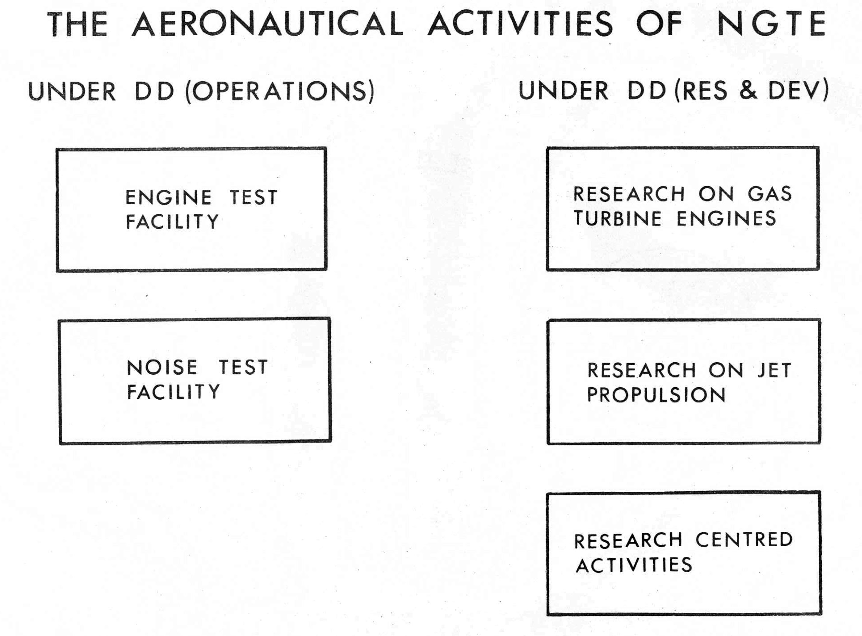
However, the total research programme s itself less than half of the
Establishment activity for, setting aside the non-aeronautical interests,
the work of NGTE as a whole is as shown in Figure 1. This diagram is functional
and does not reflect organisation which can be dismissed with the observation
that DD(Operations) is the Chief Engineer and DD(R&D) the Chief Scientist of
the Establishment. There is, however, no fragmentation in the workings of the
whole. Not only does the staff move freely between the various blocs depicted,
but the practical links between these are so numerous that if illustrated they
would make the illustration look like a "cat's cradle".
|
|
FIGURE 1
|
Whilst such a talk as this should aim to present an account of the Establishment
that is based on interesting features in its past and present activities, it
will be realised that in the time available only very few examples can be
considered. To set these in context, a certain amount of attention must
therefore be given to the underlying structure and functions.
THE RESEARCH AREA
Although, granted its changes in name and constitution, NGTE was in fact the
technological source of the World's aeronautical gas turbine and jet propulsion
industries, and although gas turbine based technologies will continue to expand
for many more decades, the current modus vivendi involves a less overt role in
collaboration with a wide range of industry including Rolls-Royce, SNECMA, MTU
and the UK airframe and component manufacturing companies. In the project world
NGTE is a UK Government test station, a specialist laboratory, an official
consultant and an agency for the execution and overseeing of publicly financed
research.
From such a set-up one may deduce that the purpose of the research programme is
the advancement, not of science, but of technology. Also that NGTE will not
necessarily conduct the research, only ensure that it is done. In practice
the research leading to or concerned with particular projects is generally
sponsored in industry and that of a basic nature in the universities.
Intramurally, the Establishment retains a middle slice together with certain
items that require such massive specialist equipment as the Engine Test
Facility, or that may be connected with possible legislation; for example
matters relating to airworthiness, noise control, or atmospheric pollution.
In Figure 2, which gives the names and functions of the six research departments,
it may be seen that the name of a department may not closely describe its
activities. For example the term "Installation Aerodynamics" in Engine
Research covers all aspects supersonic and subsonic intake and exhaust systems,
including considerations of wave and form drag and the special problems of
variable pitch fans, thrust reversers, exhaust gas and foreign object ingestion
etc. In the other half of that department, the work on powerplant dynamics
and control, including fuel systems exercises a quite different set of skills.
As Engine Research is a typical research department comprising some 20
professionals, it can be seen why not only the group as a wholee but most of
its 20 members are required to be multi-disciplinary in their scientific
outlook and its practical application. This requirement for the rounded man
rather than th e specialist, for the scientific engineer rather than the
engineering scientist, is a prime characteristic of the Establishment.

|
|
FIGURE 2
|
As such people cannot be found, one of the continuing NGTE activitics is
their training from an initial base of engineering science, physics or
occasionally mathematics, chemisty or metallurgy.
From the detail of Figure 2 it will further be seen that the disciplines of
aerodynamics, physics, thermal engineering & etc are practised by more than one
department, so that each member of staff is able to move naturally around the
territory of that illustration in the formative first ten to fifteen years of
his or her career.
As might be expected from such staff mobility in a multi-disciplinary operation,
the "Old boy net" ensures extensive collaboration between departments that
extends not infrequently to the sharing of equipment and in which the Performance
and Design Research Department plays a central part. Whilst this stems largely
from its formal responsibilities for projected powerplant assessment, the
engine architectural aspects of the design research activity also strengthen the
role. But it should be observed that there is no question of any department
becoming primus inter pares. Each is interdisciplinary and each is led by
senior staff who have served in one or more of the others, so that any professional
rivalry is of a healthy kind that promotes the cohesiveness which is so essential
to a stimulating environment. And of course that cohesiveness is by no means
restricted to the DD(R&D) area, but embraces all the functions of Figure 1
together with the non-aeronautical interests.
Another characteristic of NGTE and one which tends to strengthen cohesion is that
Performance and Design Research is not the only department that deals with the
powerplant as a whole, three others being Engine Research, Acoustic
Aerodynamics, and of course the Engine Test Department under DD(Operations).
Thus the staff in each of those departments is concerned not only with
scientific problems, but has need to test, tease and otherwise deal with a wide
variety of engines of which the Establishment is wont to run (and occasionally
break) not a few in the course of a normal year's work.
To illustrate the way in which a new research situation is approached it is
necessary to consider only one example - the NGTE history in aircraft noise
research.
THE NOISE RESEARCH ACTIVITIES
The Establishment's first major task in the aircraft noise field was self
appointed, psycho-acoustic and began with the Transatlantic operation of the
Boeing 707-120 in 1958; for although that aircraft constituted a noise problem
that could not be denied, the measure of its acoustic output on an unweighted
decibel (dB) scale was not exceptional.
Whilst the appropriately weighted Perceived Noise Decibel (PNdB) scale had
already been proposed and in some measure tested by Bolt, Beranek and Newman
Inc, consultants to the Port of New York Authority, the real problem was not
to devise a scientific measure but to establish one that would be politically
acceptable throughout the Western World. As an acceptable unit of measurement
must precede any meaningful analysis of aircraft noise, which study must in
turn lead the research towards its reduction through the evolution of quieter
engines, NGTE therefore entered the noise scene by pioneering a new style
of phsycho-acoustic experiment in which:
- The subjects were phsyiologically random members of the general public.
- Their random selection was ensured by coercion rather than attraction.
- There was no foreknowledge of the experiment on the part of the subjects.
- Psychological conditioning ensured that the result was a measure of purely physio1ogica1 response (thus
ensuring accurate, repeatable, objective results).
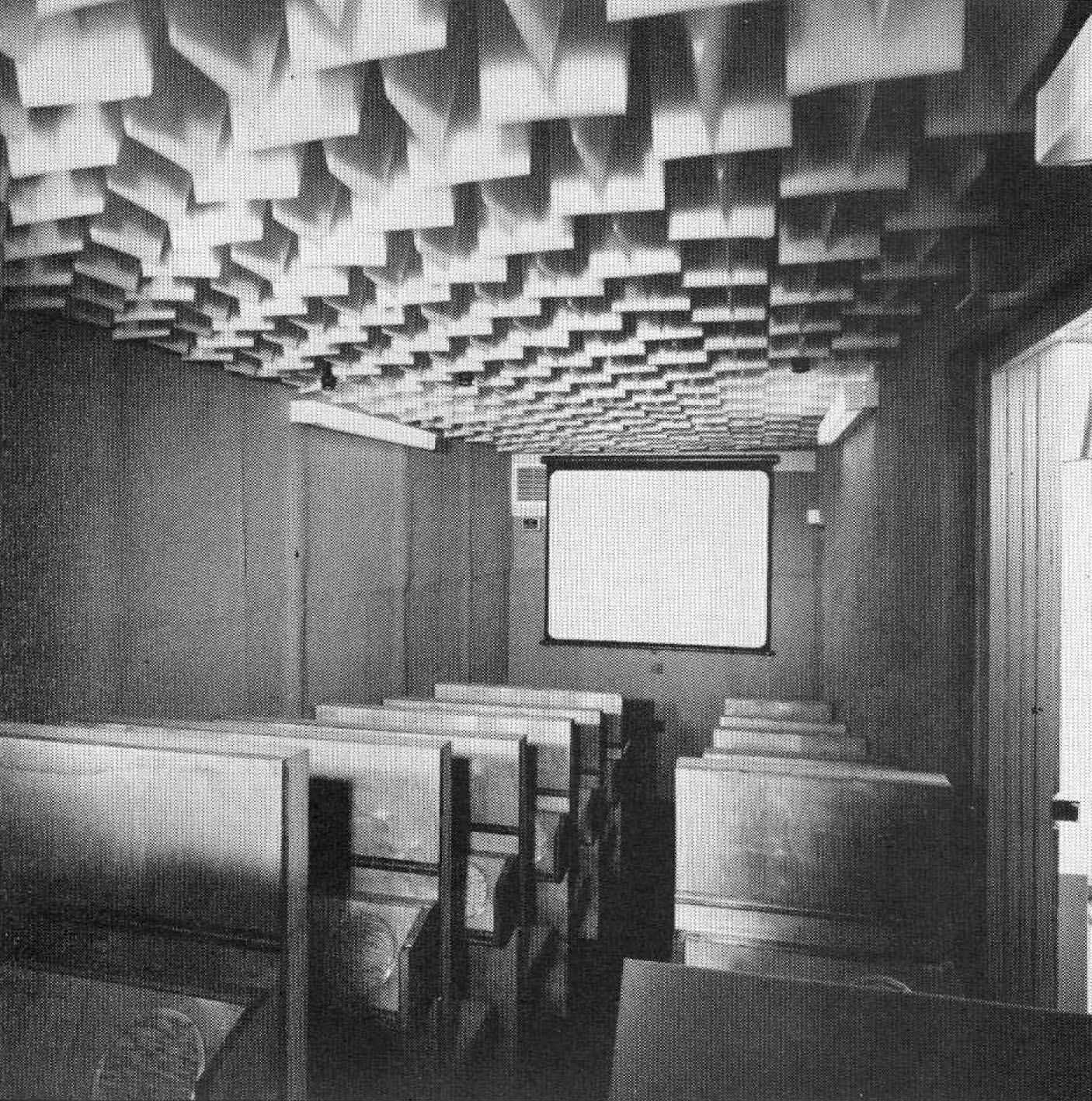
The resulting series of experiments ran from 1959 to 1968, involved many
thousands of subjects and covered all aspects of both fixed wing aircraft and
helicopter rotor noise. In this way it established both the proposed PNdB scale
that is now widely used for aircraft noise control and the proposed Effective
PNdB (EPNdB) scale that was ratified by the International Standards Organisation
as the basis of state legislation on both sides of the Atlantic. Figure 3 shows
the interior of the mobile psycho-acoustic laboratory.
|
|
FIGURE 3
|
Once that assessment technique was launched, the Establishment moved into the
business of understanding and controlling, one-by-one, the many diverse sources
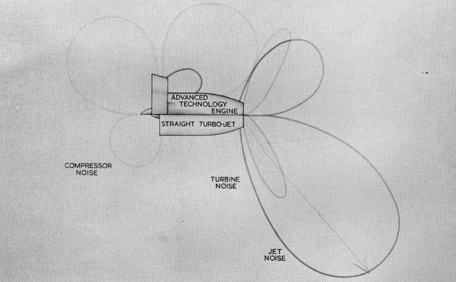
of powerp1ant noise. By way of a product, Figure 4 illustrates the advance
that was made between 1959 and 1972, and in this two features may be noted:
- The reduction in overall noise as measured by the worst polar 'balloon'.
- The extent to which the noise pattern has been balanced by adjusting the sizes of the individual 'balloons'.
|
|
FIGURE 4
|
To achieve this effect work was required on a very broad front and, in turn,
this demanded comprehensive facilities as well as extensive collaboration with
other organisations. Indeed, it should be made clear at this stage that, however
measured, less than one quarter of the necessary research was in fact executed
by NGTE, the bulk having been sponsored in industy and the universities.
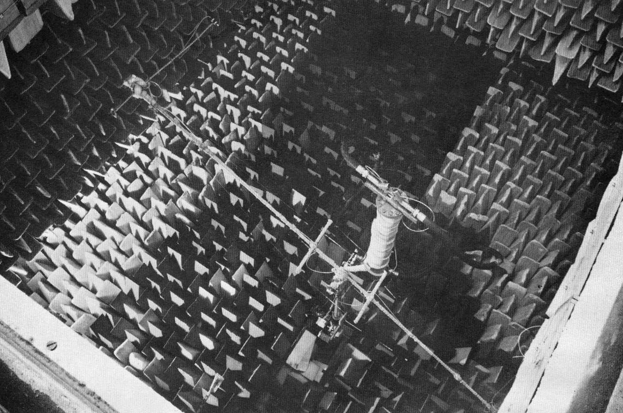
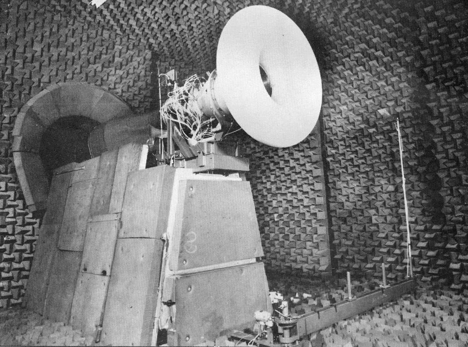
Nevertheless, whoever may be conducting the research, facilities are required
for the measurement of the fore and aft lobes of fan noise and for the sound
emanating from the after end of the engine, with special arrangements for
discrimination between the divers noises of the turbine, the jet pipe
furnishings and of course the jet itself. In addition some facility is needed
for the measurement of the aero-acoustic performance of the sound absorbing
structures that may be used to reduce the noise output from all of those sources
except the propulsive jet. All such equipment is provided at NGTE and
illustrated here in Figures 5 to 8, of which the last shows the largest
anechoic chamber in course of construction as it is not due for completion
until November 1973.
|
|
FIGURE 5
|
|
|
FIGURE 6
|
The extent of collaboration is illustrated by Figure 9, which depicts the
distribution of the Government sponsored, NGTE managed aircraft engine noise
research programme in UK over the many university, industrial and government
laboratories concerned. Indeed, even this does not paint the broadest picture
as, where international projects are concerned, there is appreciable ad hoc
collaboration with Europe.
That account of the noise activity, covering everything from psycho-acoustics
to propagation studies, from helicopter rotors to jets and from the conduct
of basic research to the monitoring of a national network is an indication of
the manner and extent of the NGTE involvement in aeronautical affairs through
its Acoustic Aerodynamics Department. As comparable policies prevail in respect
of the other five research departments, multiplication by six to account for the
rest of Figure 2 affords a reasonable measure of the total research based NGTE
involvement with UK, European and World aeronautical affairs.
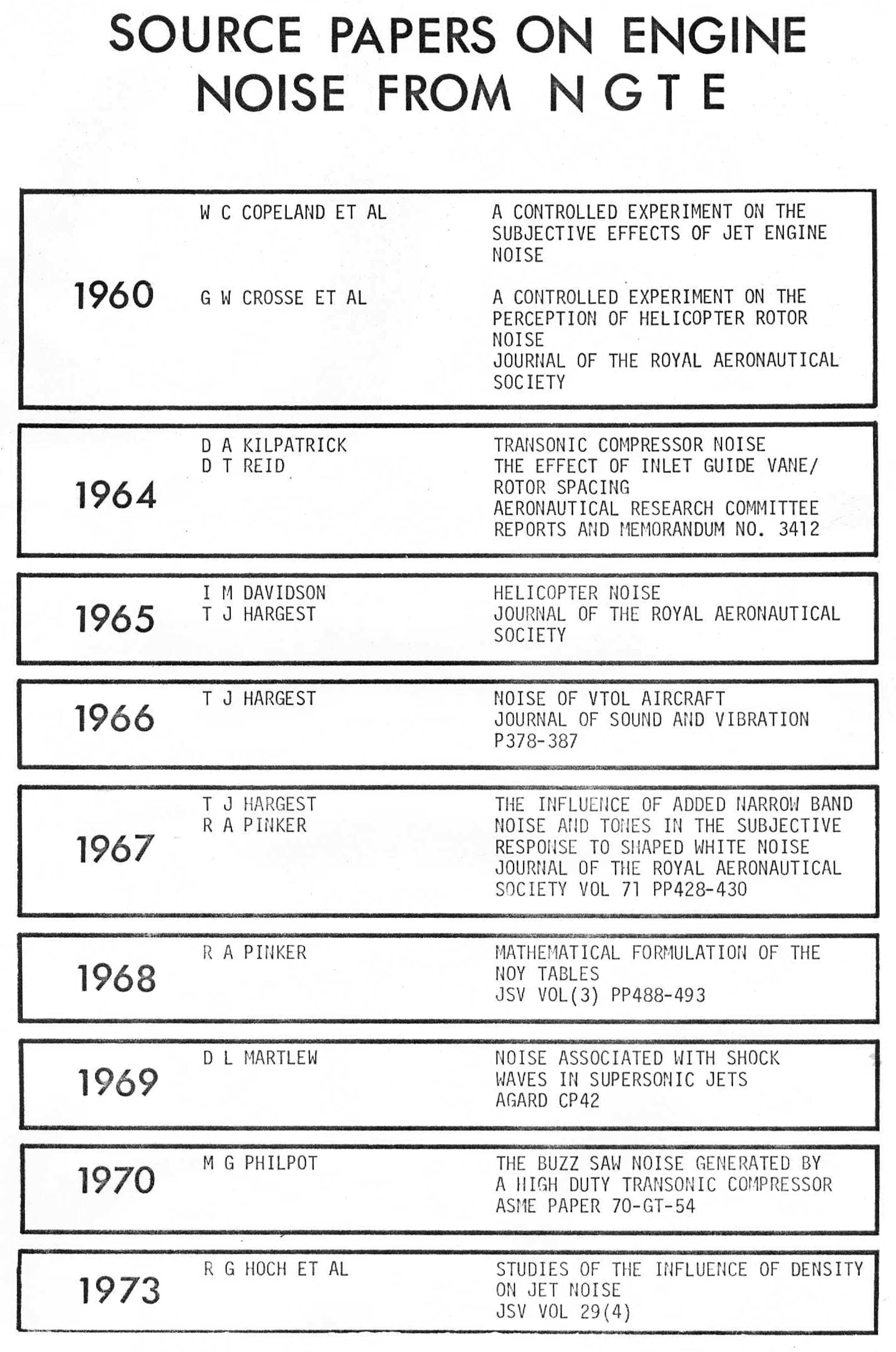
But, lest one should form an impression that NGTE leads only from behind,
Figure 10 comprises a list of those among the NGTE published titles that can
justly be deemed source papers in the noise field.
|
|
FIGURE 10
|
THE OPERATIONS AREA
As the new aero-acoustic absorption (Figure 7) and anechoic (Figure 8) facilities
together constitute a National Noise Test Facility (NTF) that is managed by the
Operations Group as a centre open to all interested parties, rather than as just
an NGTE laboratory, the Operations area has already been touched upon. But, as
Figure 1 suggests, the Engine Test Facility (ETF) is and must remain the
principal unit in that domain.
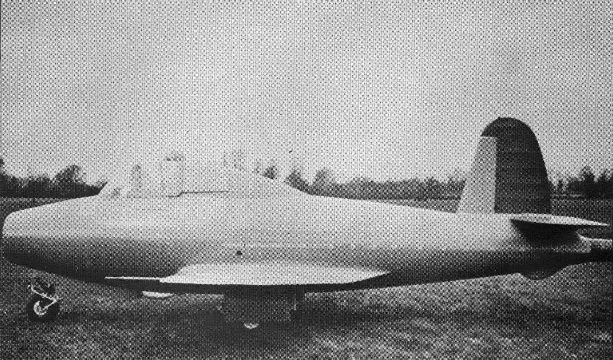
Originally NGTE had a Flight Test Section that incorporated a wide variety of
aircraft, starting with the original E28/39, Figure 11, and F9/40 or Meteor.
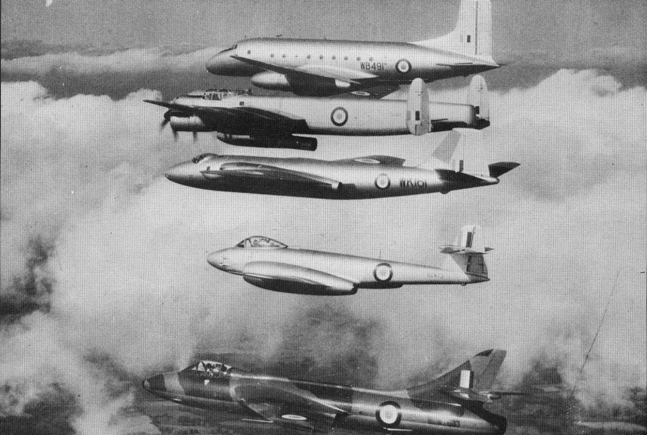
Figure 12 shows the Ashton and Lincoln flying test beds in formation with the
rest of the flight - Canberra, Meteor and Hunter - in 1958. There was also a
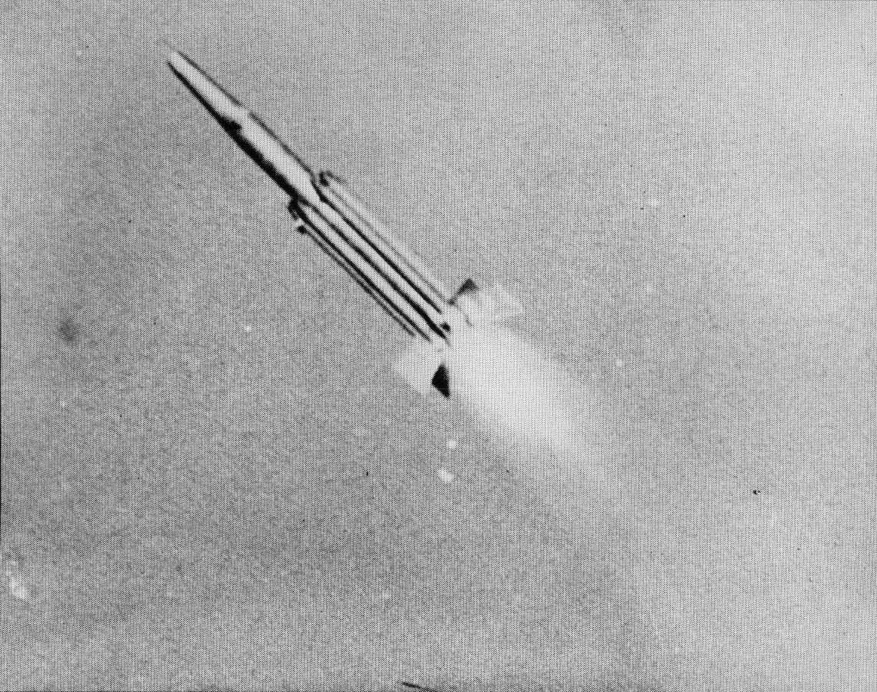
Ram Jet Section that mounted its firing trials at the Royal Aircraft Establishment
rocket range at Aberporth in Cardigan Bay, Figure 13. So far as on-site plant
was concerned there was at that time among the several air supplies none that
exceeded a calibre of 120 lb/sec at a pressure ratio of 6.0, and so virtually
no alternative to flight testing engines and other powerplant components in
aircraft.
|
|
FIGURE 11
|
|
|
FIGURE 12
|
|
|
FIGURE 13
|
The relevant change of policy took effect in the early 1960's when the Flight
Section was disbanded and 'flight' testing was transferred to a ground complex
that has become known as the Engine Test Facility and now has, so far as is
known, a combination of calibre and flexibility that is unique in the world.
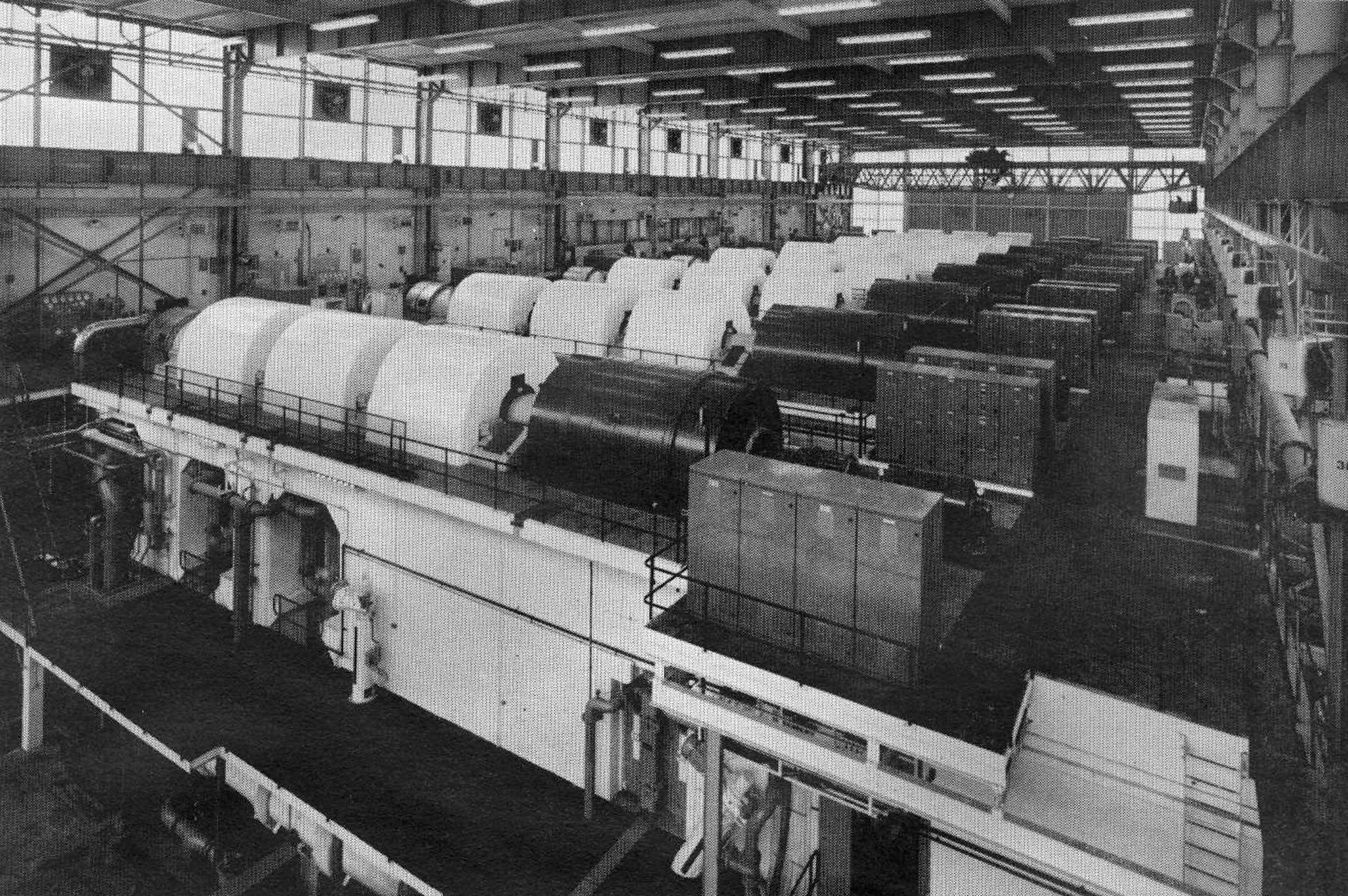
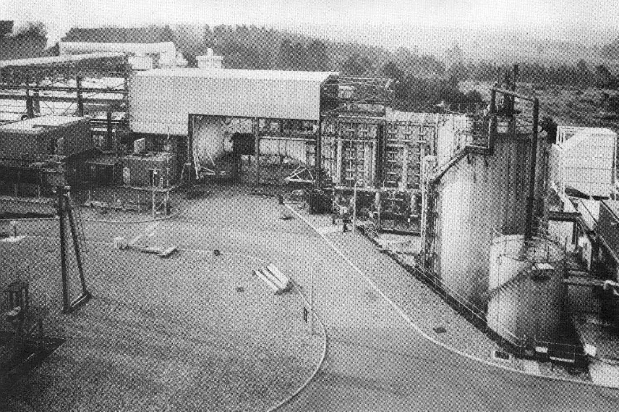
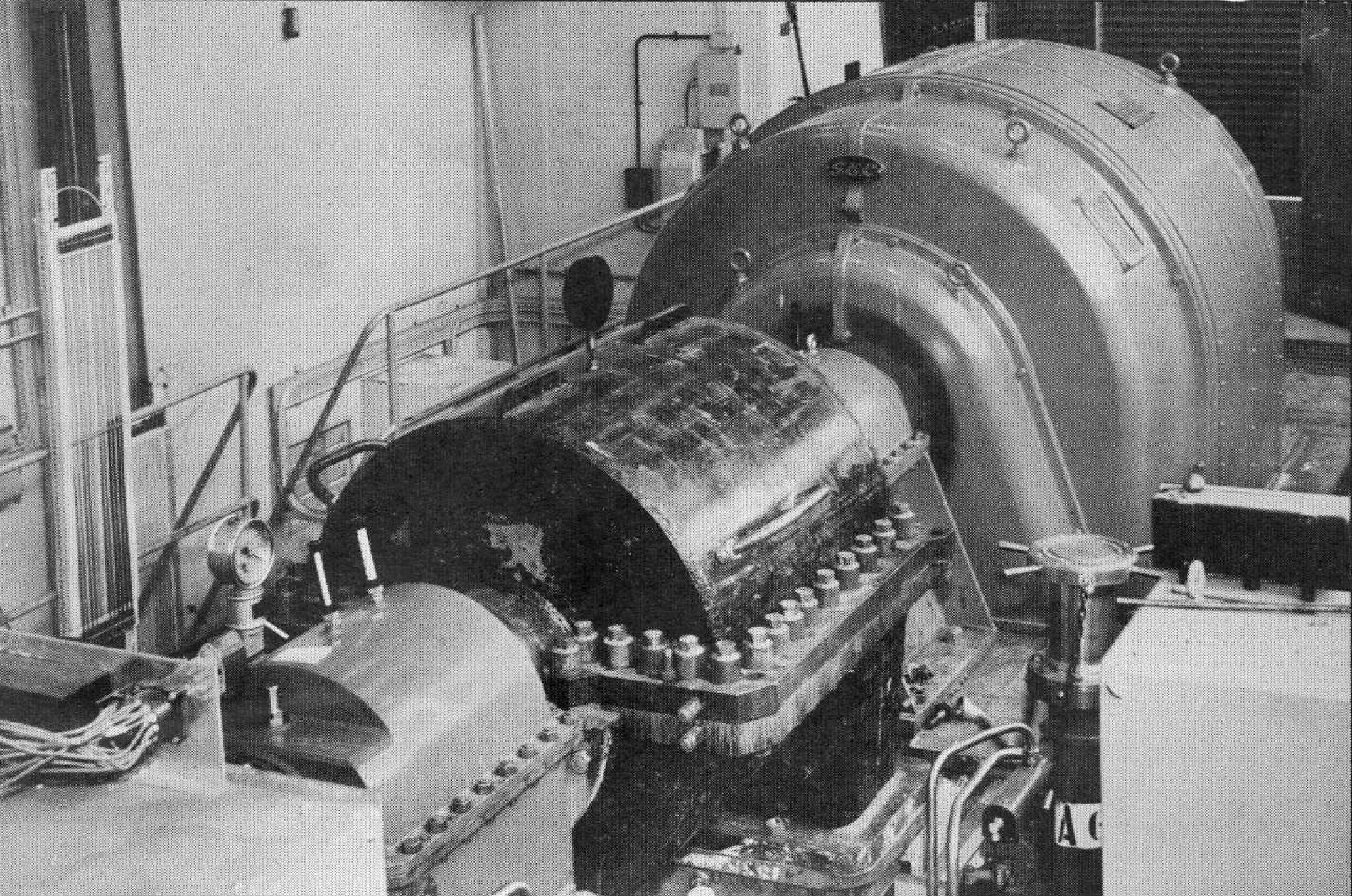
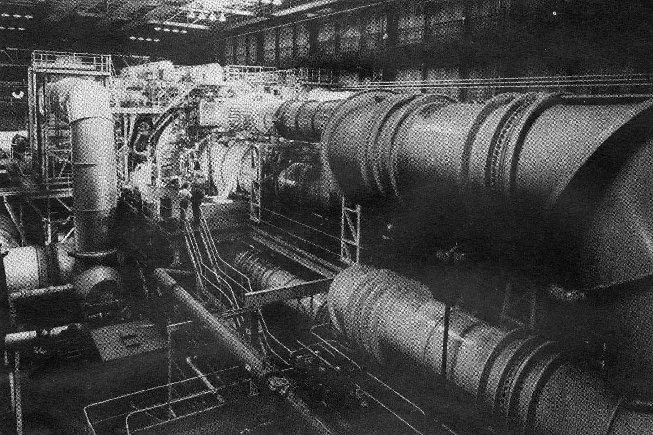
The heart of the complex is an air house, Figure 14, that contains eight
three spool compressors each of which is rated at 44,000 shp and, by an
appropriate selection of valves, can either exhaust or pressurise (ie suck
or blow) the test cells.
|
|
FIGURE 14
|
With the addition of two later air houses, both of which provide exhauster
capacity only, [Number 9 Exhauster and
Number 10 Exhauster] the total air moving capacity exceeds 1,700 1b/sec and the
available, modular sink or source pressure levels are:
- On suction: 1/81, 1/27, 1/9 and 1/3 atmospheres
- On pressure:
3 and 9 atmospheres
As this plant can, and indeed normally does suck and blow at the same time,
there is thus a limiting pressure ratio of over 700 to 1 available without
aerodynamic pressure recovery. Whilst such extreme conditions will rarely
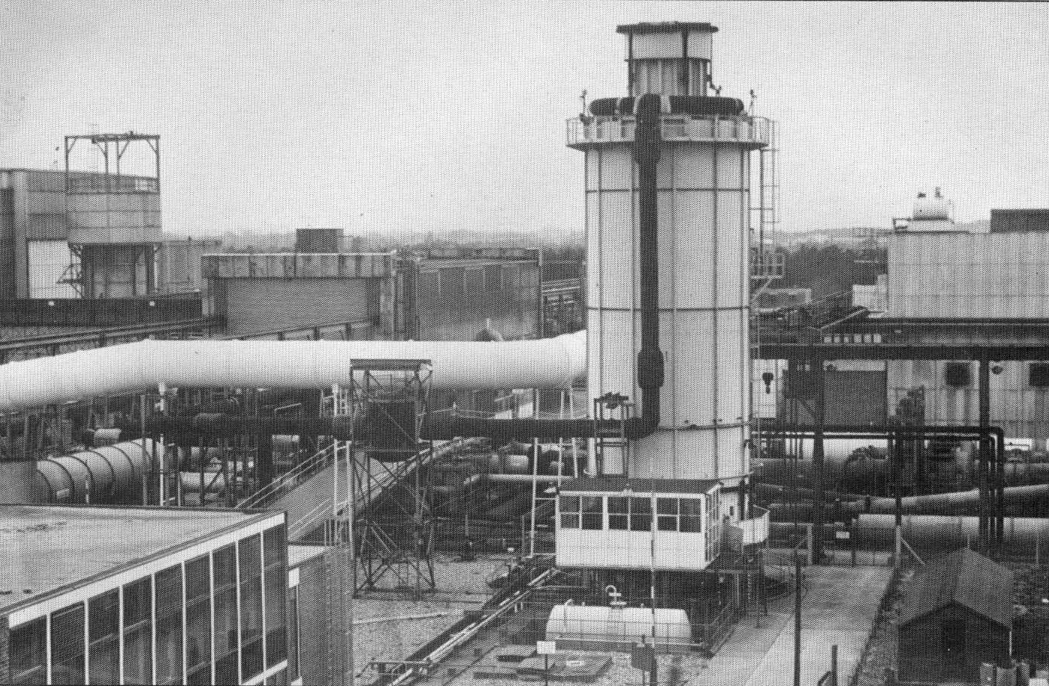
be required, it may be noted that the complex also includes much heating,
Figure 15, cooling, Figure 16 and icing, Figure 17, equipment, so that
engine tests can include a full range of wet and dry icing conditions and
an inlet temperature range from -70°C to +600°C.
|
|
FIGURE 15
|
|
|
FIGURE 16
|
|
|
FIGURE 17
|
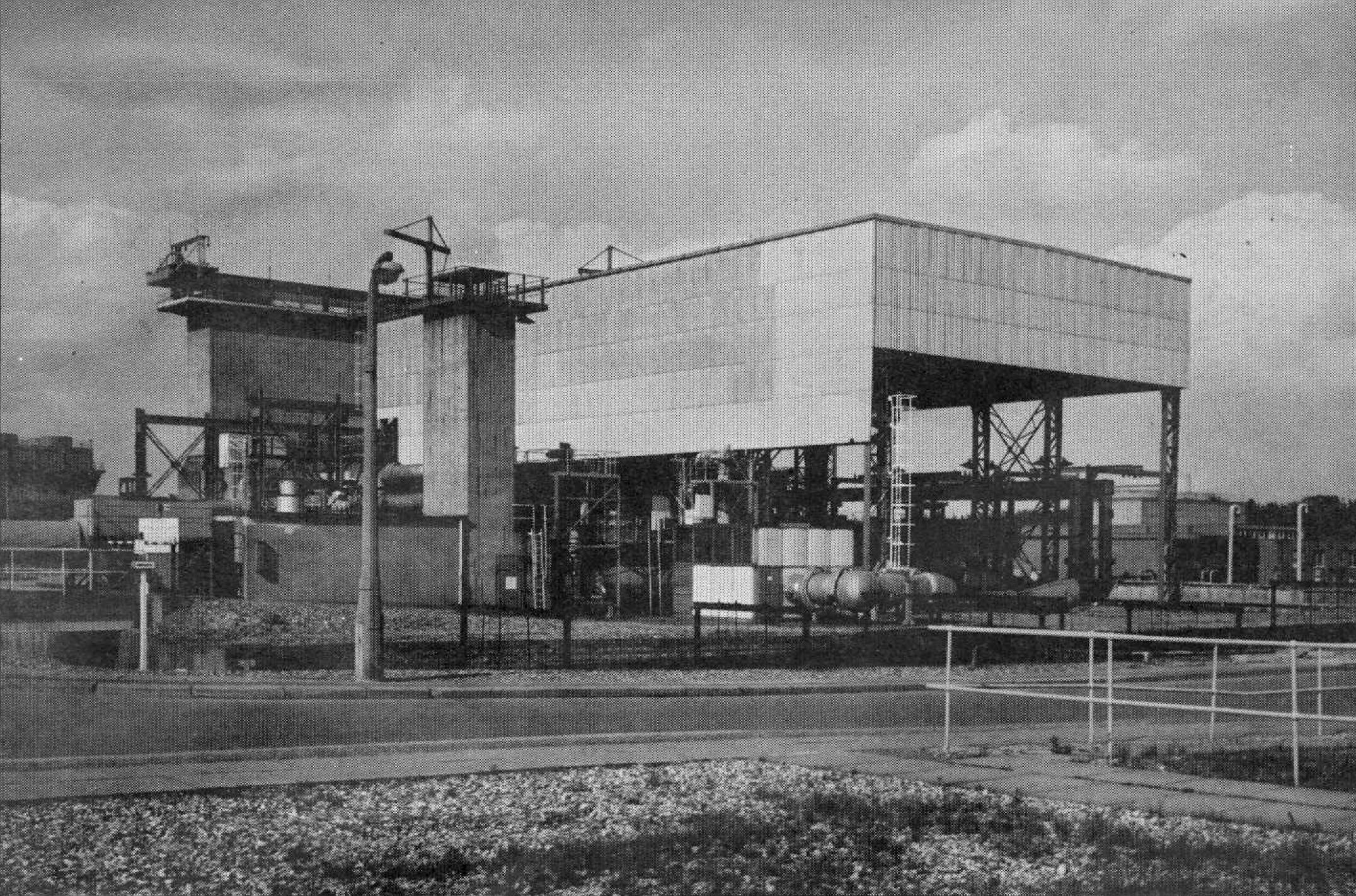
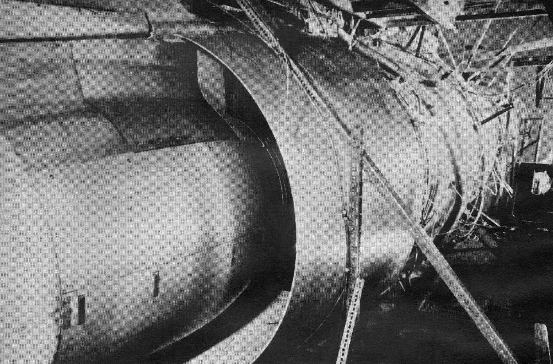
The test cells themselves are five in number, each having been developed to
meet some specific need and so being different from its fellows. The only
ones that constitute a pair with some degree of interchangeability are the
12 ft diameter cells, 1 and 2, Figure 18.
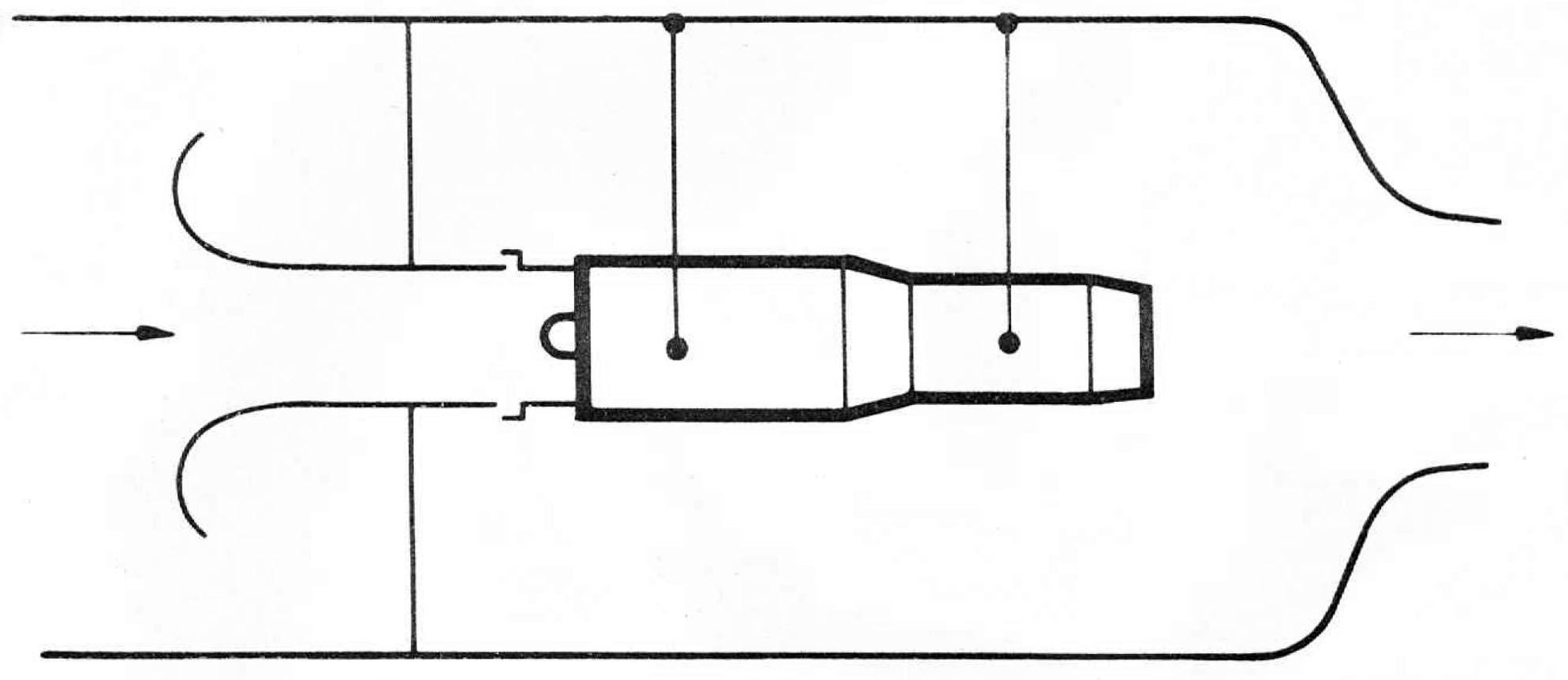
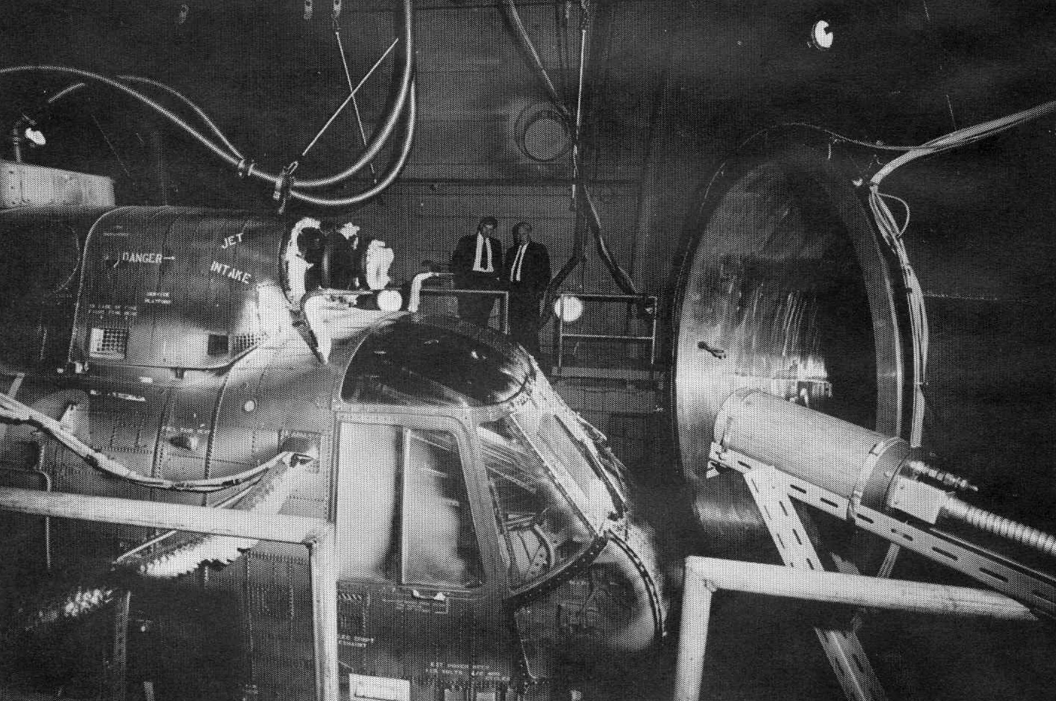
Normally, however, Cell 1 is run
as a free jet cell and Cell 2 in the connected mode. In this latter technique,
Figure 19, the engine on test is coupled to an air supply with extensive inlet
survey instrumentation, so that thrust can be measured accurately with correction
for all inlet momentum effects & etc. The simulation of flight conditions is
therefore by an appropiate scheduling of pressure, temperature and, where
appropriate, icing conditions.
|
|
FIGURE 18
|
|
|
FIGURE 19
|
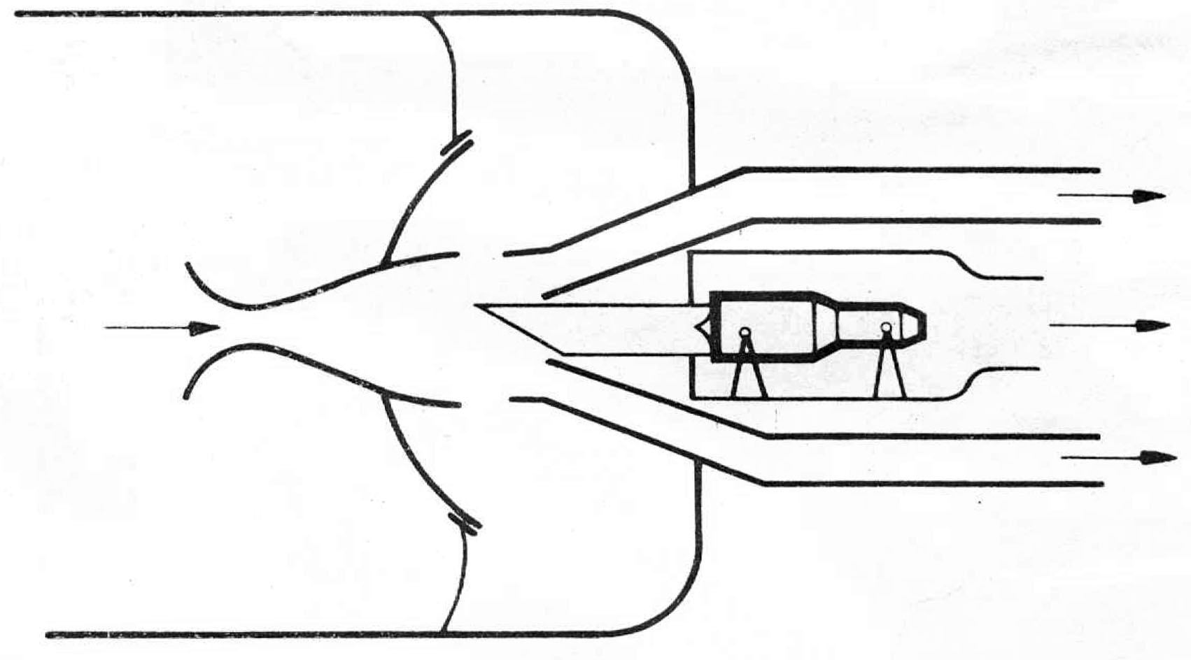
In the free jet mode, Figure 20, there is no thrust measurement but the cell acts
as a propulsion wind tunnel in which the engine, or on occasion the model is
'flown' in a free jet that may be supersonic, transonic, Figure 21, or of course
subsonic as appropriate. The limitations of Cells 1 and
2 are that they cannot
accommodate engines of larger calibre than the Pegasus, Figure 22, and that
their flight simulation is static rather than dynamic. That is, when the 'flight'
Mach number, altitude or angle of attack is changed, the transition from one set
condition to another is by a route that is not meaningful in flight and
represents 'dead' testing time.
|
|
FIGURE 20
|
|
|
FIGURE 21
|
|
|
FIGURE 22
|
For dynamic environmental testing in which such aircraft motions as pitch, yaw
and the variation of pressure and temperature during acceleration or deceleration
can be reproduced in real time one uses the larger cells of which Cell 3, Figure
23, is the first. This was first used in earnest on the ill fated TSR2 project,
is 20 feet in diameter, will take all but the largest big-fan engines and is
normally used in the connected mode. An indication of its range is that it can
cover almost the entire flight envelope of Concorde or of any military aircraft
that can reasonably be envisaged, the exception being altitudes under a few
thousand feet for which testing on a sea-level bed such as the Glen Test House,
Figure 24, will suffice. Whilst Figure 23 showed the 'flange-to-flange'
Olympus 593 engine for Concorde being lowered on to the thrust frame,
Figure 25 shows the simulated aircraft nacelle in position for environmental
trials including all the accessories and cabin air conditioning equipment
etc.
|
|
FIGURE 23
|
|
|
FIGURE 24
|
|
|
FIGURE 25
|
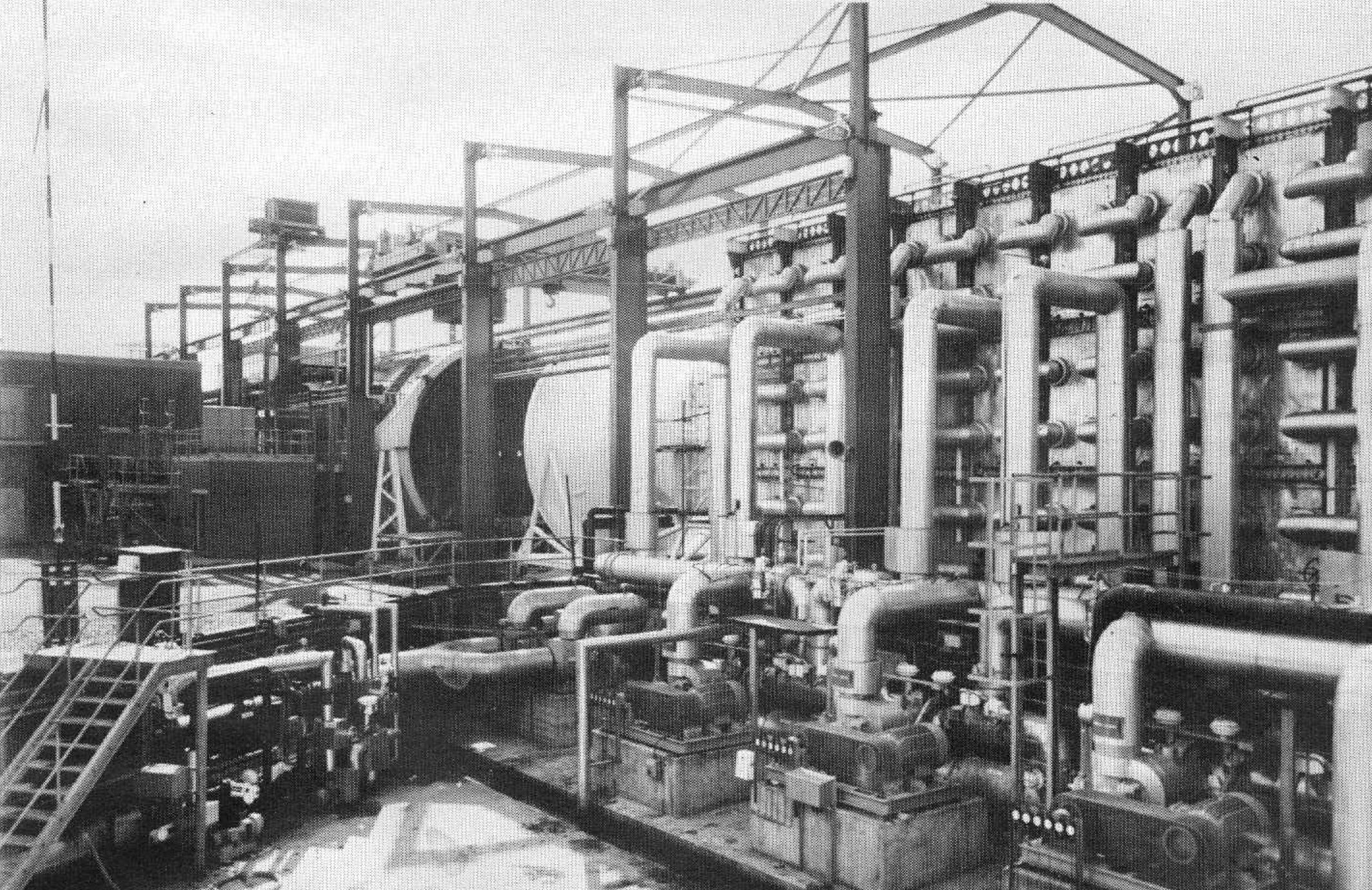
For big fan engines such as the RB2ll, Cell 3 West, Figure 26, was constructed
with a diameter of 25 feet and, as Figure 27 shows, such tests are done in
the connected mode with the engine thrust frame. Again, virtually
the whole flight envelope is covered and indeed, because of its size, flow
and icing capability, Cell 3 West is also used in the free jet mode for
airframe trials - Figure 28.
|
|
FIGURE 26
|
|
|
FIGURE 27
|
|
|
FIGURE 28
|
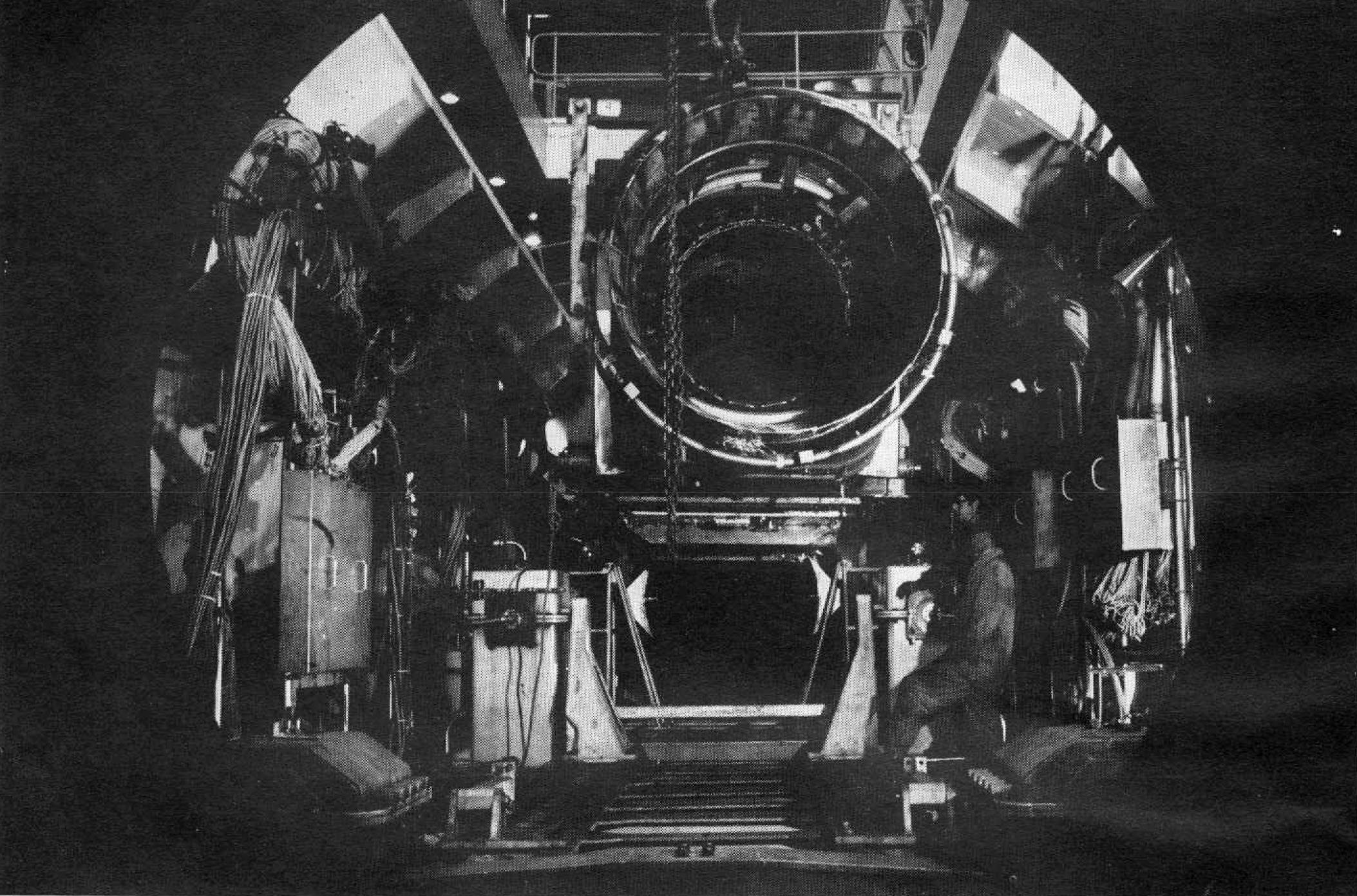
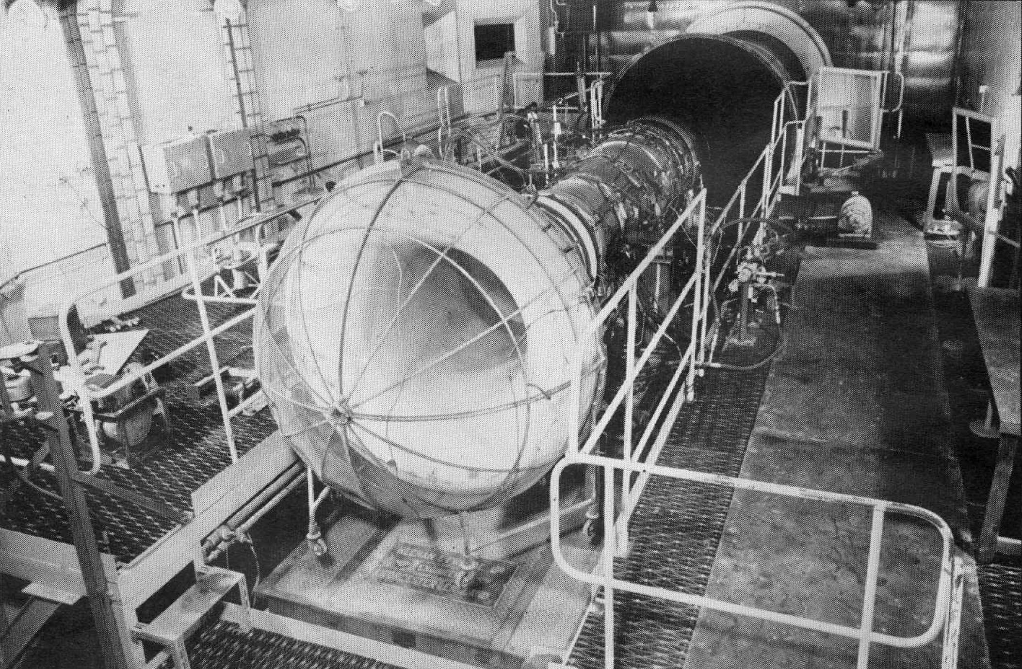
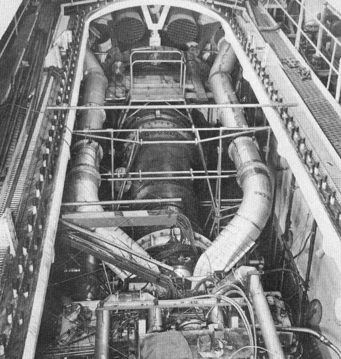
Cell 4, the supersonic free jet cell, Figure 29, is the largest of all and
was itself an engineering project that took 11 years of R&D, design and
construction from its conception to its commissioning. The whole structure
is some 400 feet long with a plenum chamber diameter of 30 feet and a Mach
number range up to 3.5 at which the inlet temperature is 470°C for correct
flight simulation. In covering the flight envelope of an aircraft like
Concorde the cell reproduces all significant dynamic conditions including
acceleration and pitching and yawing manoeuvres of which the rate is up to
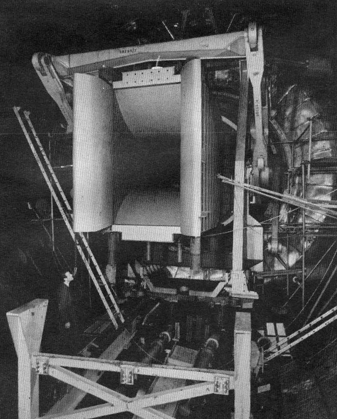
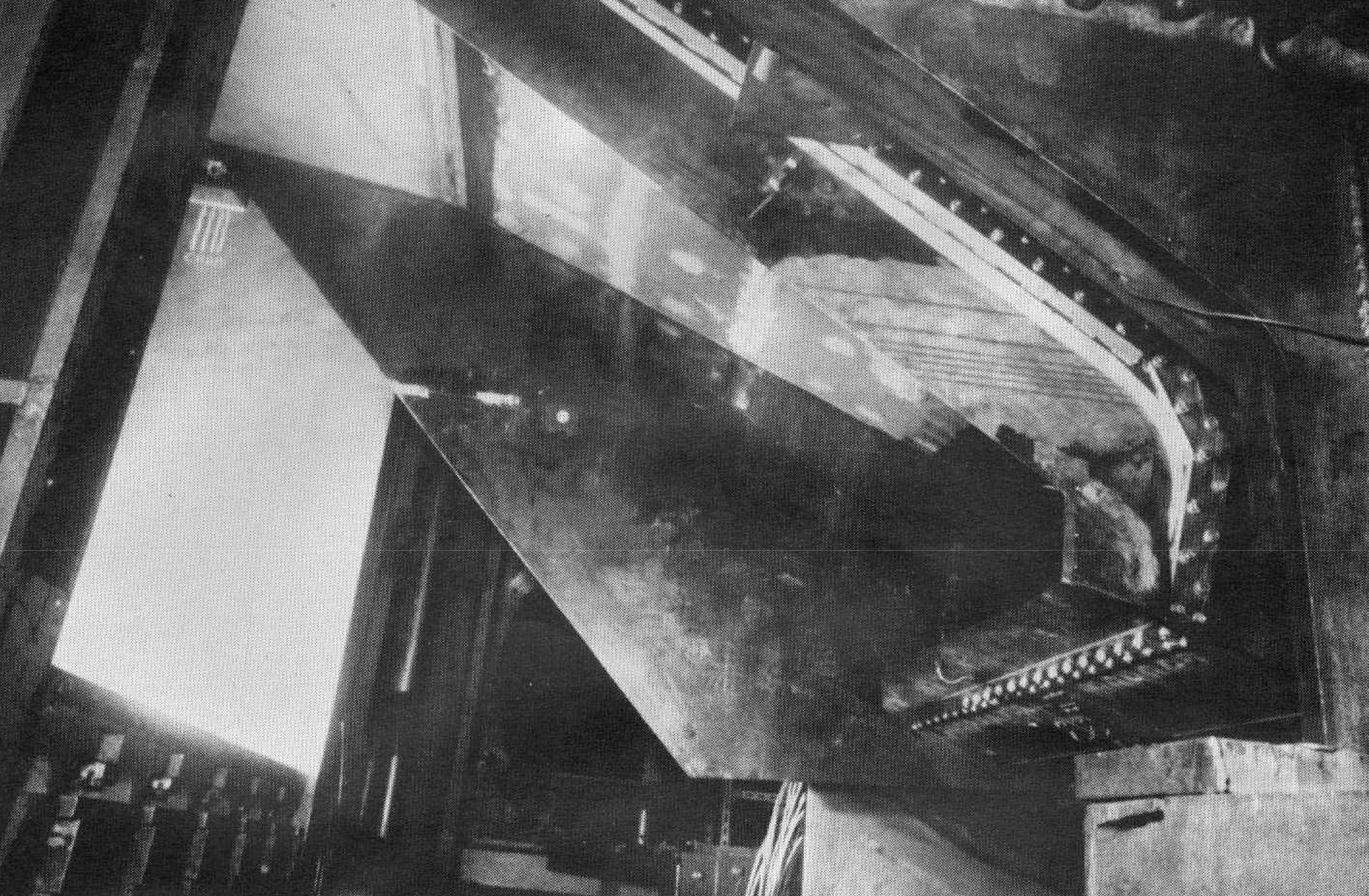
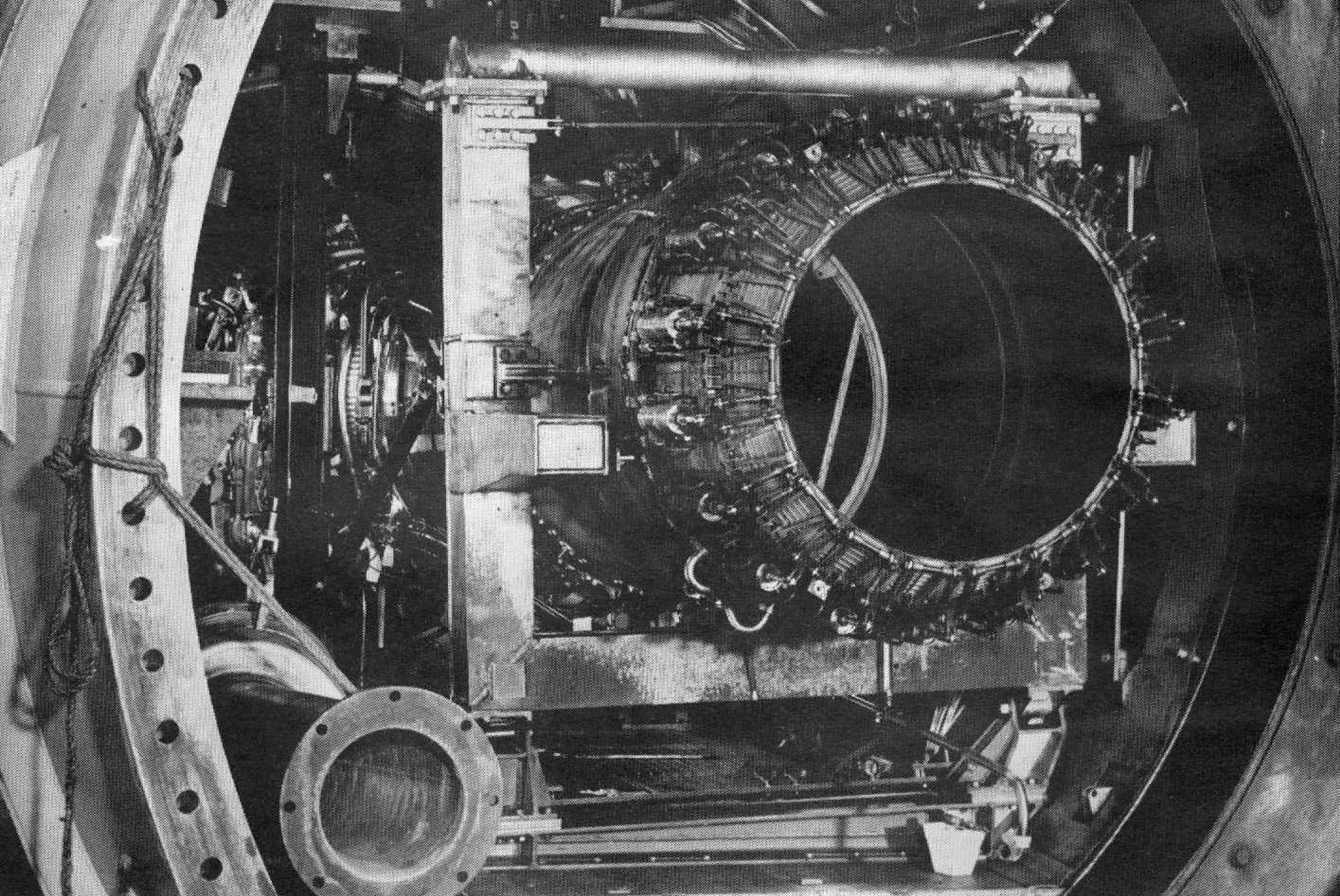
10 degrees per second. Figure 30 shows the inlet of the 75 ton variable
Mach number nozzle with its pitching and yawing machinery, Figure 31 the
outlet end with the Concorde intake in position in its shock diamond and
Figure 32 the inside of the engine capsule.
|
|
FIGURE 29
|
|
|
FIGURE 30
|
|
|
FIGURE 31
|
|
|
FIGURE 32
|
From the fact that the equipment of the Engine Test Facility is used not only for
development trials but up to 20 per cent by the research departments which also
have their own facilities including air supplies that total over 200 lb/sec
and range from 1/15 to 50 atmospheres pressure with appropriate temperatures
to match, it may be appreciated that NGTE enjoys a considerable and in several
respects unique technological resource on its 200 acre NGTE site at Pyestock.
Indeed the measure of its plant is a fourth feature which makes NGTE unusual
among research establishments.
It may serve as a reminder of the first three features of scientific catholicism.
overall cohesiveness and a 'down-to-earth' approach to engineering hardware, to
note that the following film was made in 1968 by the Combustion and Instrumentation
Department to present a research of the Engine Research Department at the request
of the Acoustic Aerodynamics Department that required it for the last of their
subjective noise measurement experiments on members of the public.
(HERE WAS SHOWN "A BRIAN FOR THE JET ENGINE"; 15 min, 16 mm COLOUR)
With thanks to Richard Pinker for the scans
|