|
 | Electrical, Steam, Water And Fuel Services |
5.1 Plant Services For Gas Turbine Testing
Certain essential services are required to effectively operate the test plant and
equipment described in the preceding sections; these services are an integral part of the
N.G.T.E. Test facilities without which few of the tests would be possible. This is
particularly true of the major test cells where the sophisticated test equipment requires the full
range of these services.
These services are:-
- high voltage electricity supply and distribution
- high pressure steam supply and distribution
- raw and treated cooling water supply, drainage and effluent treatment
- fuel supplies for engines, and steam raising plant
Although it is not possible to explain in every detail the complexity of these
services, a description is given in para 5.2 to 5.7 of the main arteries. The figures show
pictorial views of the major plant items and also simplified supply and distribution networks
for the main services. Frequently the installed services have unique features and the commodity
consumptions are such that the N.G.T.E. has become a very large commercial user
as far as the Public Utility Boards are concerned.
The electrical distribution system is described in para 5.2. Gas turbine altitude
testing requires a very large amount of electrical power to drive the air moving plant. While the
maximum capacity of the electrical supplies to the N.G.T.E. and the Royal Aircraft
Establishment (RAE) are rated at 180MW, economics make it necessary to set the maximum demand limit as
low as possible. By considering the forthcoming test program and any financial restraints in operation
at the start of each financial year, co-incident plant peak demands which incur heavy financial
penalties are avoided. The maximum demand is agreed annually; the present (1981) maximum demand
being 115MW (included the RAE).
As the electrical power generated by the N.G.T.E. is mainly
steam driven, there is a close relationship between steam production and electrical power consumption.
High pressure steam is also required to start and operate the G.E.C. compressor-exhauster machines
and is used extensively for site heating purposes. The Boiler House
is therefore an integral part of the the testing services.
The water distribution systems are described in para 5.5 and 5.6. Various grades of water
ranging from raw stock to demineralised water are supplied to the Engine Test Facility and steam raising
plant. The Establishment has found from experience that the use of treated water in the recirculating cooling
systems is economic as maintenance costs are greatly reduced. At one time N.G.T.E. water
supplies were drawn from the Basingstoke Canal; however the reservoirs today are exclusively filled
with stock drawn from the Mid-Southern Water Company. The water effluent discharges into the local
streams which are under the jurisdiction of the Thames Conservancy Board and the statutory requirements are
therefore binding on the Establishment and it working procedures must be arranged accordingly. Surface
water drainage presents few problems but effluents from the test rigs can take the form of an oil
emulsion or carry large quantities of soot. Plants have been installed to deal with both of these problems
so that effluent can conform to the statutory requirements.
The various types of aviation kerosine, heavy oil and other fuels are supplied under
contract by one of the commercial oil companies and road tankers are used to deliver to site. The
fuel is stored in a tank farm and is pumped to the appropiate local storage areas according to demand.
These services are described in para 5.7 but the description does not cover the individual
high pressure pumping arrangements which exist at most of the test cells; this equipment is considered part
of the experimental engineering which is modified to suit particular tests.
5.2 N.G.T.E. Electricity Supplies
There are two incoming power supplied and a local power station. A 132kV supply rated at
130MW during the months of November to February and 90MW at all other times, is from the C.E.G.B. Fleet sub-station
which forms part of the national 400kV grid system. This supply feeds four transformers three of which, rated
at 66MVA 132-33kV, feed three sections of the Air House 33kV
bus-bars while the fourth, rated at 30MVA 132-11kV, feeds No. 10
exhauster machine described in para 2.4. A second supply, which is at 33kV, feed directly into the
fourth section of the Air House 33kV bus-bars and
is rated at 40MW. This supply is obtained from the S.E. sub-station at Weybourne Lane, Farnham but
is programmed for change in 1982 when it will be disconnected from Weybourne and connected to the
R.A.E.
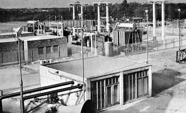
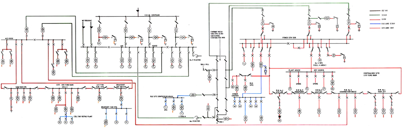
Figure 5.1 shows the S.E. sub-station at N.G.T.E. while Figure
5.2 shows the electrical distribution network.
|
|
Fig. 5.1 The Southern Electricity electrical sub-station at N.G.T.E.
|
|
|
Fig. 5.2 Circuit diagram of electrical power supplies at N.G.T.E.
|
Local power generation amounts to 18.75MW, this being generated at 11kV.
5.2.1 Distribution System
- 33kV Distribution: Two sections of the Air House
33kV bus-bars supply power to the Fairway Mesh sub-station via two 30MVA reactors. From this point
power is fed at 33kV to the Old Site also two R.A.E./N.G.T.E. interconnector circuit with a total
capactiy of 45MW are available for standy duty.
Two sections of the Air House 33kV bus-bars supply power to
two 10MVA, 33-11kV transformers local to the Air House.
The eight main exhauster-compressor motors in the Air House area
also connected to the 33kV bus-bars.
- 11kV Distribution:
- Three 33-11kV transformers rated at 25MVA, 15MVA and 5MVA are connected to the Fairway Mesh bus-bars
and supply the Power Station 11kV bus-bars. From these bus-bars
supplies are distributed to the Power Station auxiliaries 11-3.3kV
transformer, the centralised site ring main and Old Site (Note: this is an alternative feed, see (2) below
for the usual supply), Plant House machines and
No. 9 exhauster motor.
- The two 10MVA 33-11kV transformers, fed from the Air House
33kV bus-bars, feed the Air House 11kV bus-bars. From
these bus-bars 11kV supplies are distributed to the Air House
auxiliaries (four 1MVA 11kV-415V) transformers, the centralised site ring main, the E.T.F. ring main,
Air House cooling towers transformer and "D" Boiler transformer.
There are numerous 11kV-415V transformers around the site, in the 500 to 1,500kVA range, to provide normal
services to workshops, laboratories, offices, etc. In certain areas other voltages, 3.3kV and 6.6kV are
used and these are porvided via transformers from the 33kV and 11kV distribution systems.
- Air House: Each of the four sections of the Air House
33kV bus-bars supplies two of the main compressor-exhauster motors via a directly coupled 27.5MVA 33-11kV
transformer. Switching is implemented on the 33kV side in order to keep rupturing levels to reasonable
values.
5.2.2 Generating Plant
Four alternators are installed in the Power Station;
details are given in Table 5.1.
Table 5.1
N.G.T.E. Generating Plant
| Steam Turbine |
12.75MW |
11kV |
3 |
| Gas Turbine |
6.0MW |
11kV |
3 |
| Diesel |
60kW |
415V |
3 |
| Diesel |
50kW |
415V |
3 |
The 12.5MW steam turbine and the 6MV gas turbine were installed as peak lopping sets. With
the present (1981) tariff however, the pattern of operation changed. Should the C.E.G.B. declare a
Load Management Period during the period October to March sufficient power for R.A.E. and
N.G.T.E. base loads is provided by the 12.75MW and 6.0MW sets, thereby enabling
N.G.T.E. to claim a rebate from the Southern Electricity.
The 60kW diesel set is used as an emergency set if normal supplies to
certain important long term tests are interrupted for more than a pre-determined time. The 50kW
diesel set has the important function of supplying the 6MW set auxiliaries to enable the set to be
started. Once the 6MW is running an generating, the 12.75MW set can be started thus giving
N.G.T.E. the capability of being able to startup and generate 18.75MW in the
event of a loss of all external power supplies.
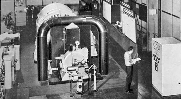
The 12.75MW alternator is also used as a variable frequency source to start the
36,000 h.p. synchronous motor driving No. 9 machine. The
two machines are run up to grid frequency by increasing the turbine spped and then synchronised with
the grid. The starting operations on both machines from barring spped are fully automatic. Once
the two machines are synchronised with the grid, the alternator can be shut down and/or other
facilities can be operated form the section of the bus-bar used to couple the two machines together.
|
|
Fig. 5.3 The 12.75MW steam driven Bellis and Morcom generator set
|
5.3 Cost and Limitations to Plant Utilisation due to Electrical Power Supplies
It is very important to note that various electrical restrictions limit the
manner in which the whole of the N.G.T.E. plant can be utilised.
The electricity tariff which has been negotiated between N.G.T.E.
and S.E. is similar to that operated by other large power users. It consists basically of maximum
demand charges to cover the cost of capital equipment and unit charges to cover operating costs.
As with most other commodities, the laws of supply and demand apply, and so these two basic charges
vary. In winter, multiple rates apply, depending upon the time of day and the month. During the
summer period of April to September, a single day rate is applicable. Between midnight and
08.00 hours a night rate applies throughout the year.
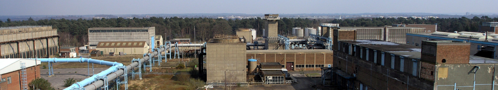
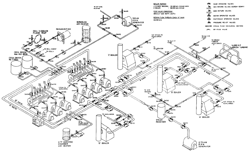
5.4 N.G.T.E. Steam Supplies (The Battle House)
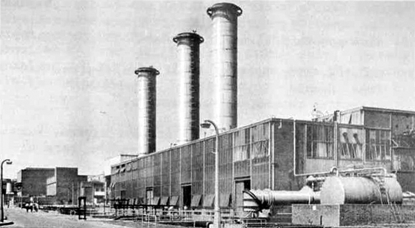
There are various demands for high pressure super-heated steam on the New Site. The
N.G.T.E. steam raising facilities comprise three marine type boilers (A, B and C boilers)
housed in a common boiler house and a fourth boiler (D boiler) sited in the open. A, B and C boilers
can each export up to 130,000 lb of steam/h while D boiler has a rated export capacity of 500,000 lb of steam/h.
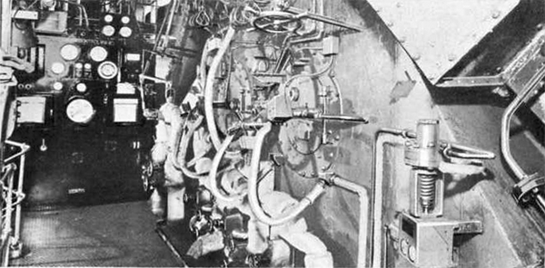
Stop valve conditions are 400lb/in2 and 650oF (343oC). Pictorial views of the
Boiler House and D boiler are shown in Figures 5.4, 5.5 and 5.6.
|
|
Fig. 5.4 The N.G.T.E. Boiler House
|
|
|
Fig. 5.5 One of the N.G.T.E. boiler fronts
|
|
|
Fig. 5.6 General view of D Boiler
|
Steam is required for the following main purposes:-
- Brush Steam Turbine, used for compressor testing. Maximum demand 185,000 lb/h.
- The Air House G.E.C. 8,000 h.p. steam turbines.
Maximum demand 64,000 lb/h of steam each set, eight machines installed.
- THe Power Station Bellis and Morcom steam turbine
generator. Maximum demand 150,000 lb/h.
- N.G.T.E. site heating calorifier system. Maximum demand 20,000 lb/h, requirements vary according to
ambient temperature.
- Air House site heat calorifier system. Maximum demand 5,000
lb/h, requirements vary according to ambient temperature.
- Heating medium for the re-activiation of the Ceca air drying
plant. Maximum demand 40,000 lb/h.
The various demands for setam do not necessarily coincide and the actual total demand
is programmed according to the Establishment's testing programme and to the ocassional need to generate
power in order to reduce the input of electricity.
Occasionally steam is required for a number of secondary services which include :-
- Atomising steam for Cell 3 air heater plant.
- Steam for de-icing Cell 3 and
Cell 4 exhaust flame-trap coolers.
- Trace heating steam for heavy residual fuel.
- Low pressure steam for a variety of experimental purposes such as the vaporising of distillate fuels
in experimental fuel systems and other research test cell uses.
- Steam for defrosting Cell 3 West air cooler.
Each of these services are provided as and when requrested through the plant centralised
booking arrangements.
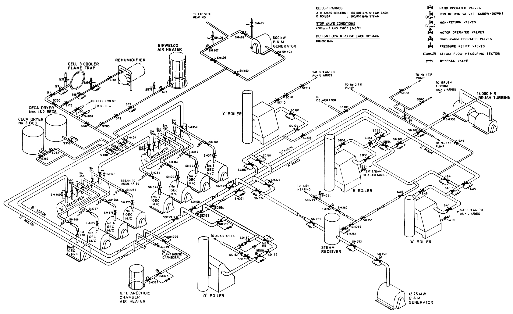
|
|
Fig. 5.7 Arrangement of N.G.T.E. high pressure steam distribution system
|
Most of the installations have a fluctuating steam demand because of their wide range of
operating conditions and the frequency with which machinery must be modulated to suit engine test programmes
and it was for this particular reason that marine boilers were originally installed at
N.G.T.E. Two of the boilers are ex-Admiralty three drum units built for Battle Class
Destroyers, whilst the third is a five-drum unit built by Messrs Yarrow and Company Limited of Glasgow.
The fourth and largest boiler (D boiler) was installed by Foster Wheeler and commissioned in 1975.
Condensate water from the high pressure steam supplies is fed back to the boilers from the
Air House and the Ceca air
drying plants through an 8 inch main. This water is continuously monitored to ensure that it is satisfactory
for re-use. Boiler feed water arrangements are described in para. 5.5.
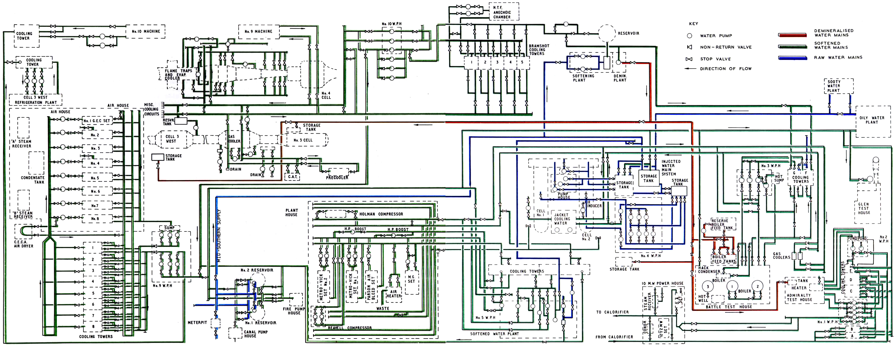
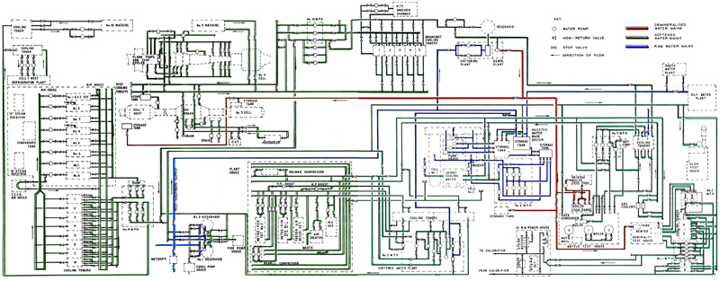
5.5 N.G.T.E. Water Supplies
The heavy plant machinery and experimental equipment required for altitude gas turbine testing
needs a plentiful supply of cooling water and for this purpose a complicated network of reservoirs, cooling towers
pumphouses and pipe circuits have been installed on the New Site N.G.T.E.. Figure 5.8 shows
the circuit diagram for this water network. Three qualities of water are provided and Table 5.2 gives a summary
of capacity for the three supply circuits while para (1), (2) and (3) give details for each grade.
|
|
Fig. 5.8 Layout of N.G.T.E. New Site water supply circuits
|
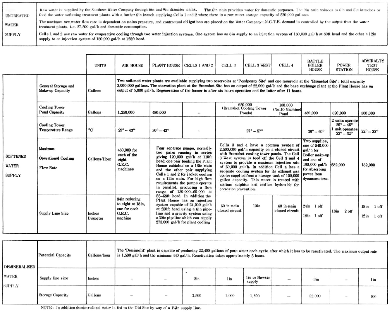
Table 5.2
Water Supplies For N.G.T.E. New Site
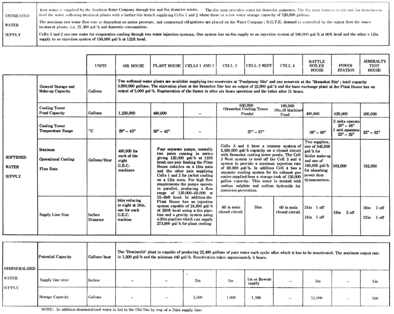
On the Old Site separate water supplies are provided for the small test cubicles which are
not described in this publication.
- Raw water: Raw water is supplied to the Establishment by the Mid-Southern Water Company via two mains;
one for supplying domestic water in the Establishment's many buildings is 6in diameter, the other, 9in
diameter, is ued to supply the site softened water treatment plants. There is however a facility for
interconnecting these two mains. Originally raw water was chosen for engine testing and general plant use,
but experience has shown that maintenance troubles and costs are reduced if treated water is used and
the systems were modified so that softened water is generally available. However, it is possible to
supply two of the N.G.T.E. reservoirs with raw water if ever there was a shortage of
softened water because of a breakdown in the treatment plants.
Because engine exhaust gas cooling in Cells 1 and 2 is wholly
by direct injection, as opposed to predominantly indirect cooling systems in most other cells,
Cells 1 and 2 are supplied direct with raw water from the 9in
main and there are available 520,000 gallon capactiy storage tanks adjacent to the test cells.
- Softened water: Although the test plant requires a high flow rate of cooling water, nearly all
tests are of limited duration and consequently the total capacity can be supplied from a storage system
which is replenished during the non-testing period. N.G.T.E. has three main reservoirs,
each having a capactiy of one million gallons, giving a total of three million gallons. Two of the reservoirs
are at the 'Pondpenny' site whilst the third is at the 'Bramshot' site. These reservoirs are continuously
filled with softened water from the treatment plants and there is a 12in bore ring main system through which the
water is distributed to the individual test plants. Most of the larger facilities have their own cooling
tower, each of which has a cooling pond which holds additional supplies of softened water. The main
cooling tower installations are given in Table 5.3.
Table 5.3
N.G.T.E. Cooling Tower Capacities
| Air House |
1,250,000 gallons |
| Bramshot (Cells 3, Cell 3 West and Cell 4) |
650,000 gallons |
| Plant House |
480,000 gallons |
| No. 10 Machine |
180,000 gallons |
| Battle House |
480,000 gallons |
| Admiralty Test House |
300,000 gallons |
| Power Station |
620,000 gallons |
| Cell 3 West Refrigeration Plant |
11,000 gallons |
| Total |
3,971,000 gallons |
The total storage capacity of softened water in the cooling ponds and reservoirs is therefore approximately
seven million gallons.
The calcium carbonate hardness value of the water in the Farnborough locality lies between 175
and 225 ppm and there are two installations used to treat the raw water stock. The larger plant,
located at the Bramshot site, uses the Starvation or HI process which reduced both the hardness and
the alkalinity. This is achieved by passing the water over ion exchange resins whihc break down the
temporary hardness and alkaline salts; this bed is regenerated with dilute sulphuric acid. The capacity
of this plant is 22,000 gal/h and it is capable of working continuously except for the reactivation
period; the plant is automatically controlled. The second water treatment plant is sited near the
Plant House, the equipment uses the base exchange process
which reduces hardness but leaves alkalinity unaffected; this plant has a capacity of 5000 gal/h
and uses brine for regeneration. Both softening plants can work together to fill the reservoirs
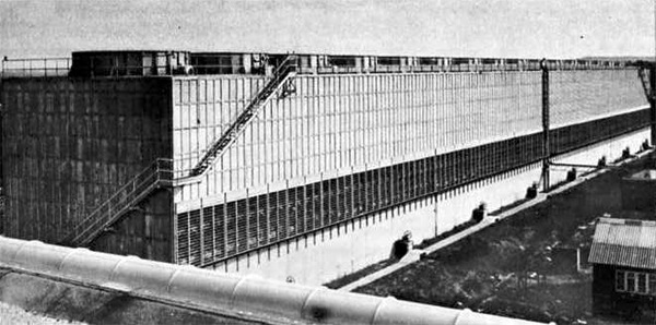
so that the toal water treament capactiy is 27,000 gal/h. Figures 5.9 and 5.10 show views of the
Air House and Bramshot cooling towers, whilst the distribution
network for the softened water is shown in Figure 5.8. The detailed circuits in the individual test
cells and laboratories are not shown but reference is made to N.G.T.E. drawings
and handbooks which give detailed information for the areas concerned.
|
|
Fig. 5.9 Air House G.E.C. Cooling Towers
|
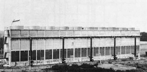
|
|
Fig. 5.10 Cooling Towers for engine exhaust in Test Cells 3 and 4
|
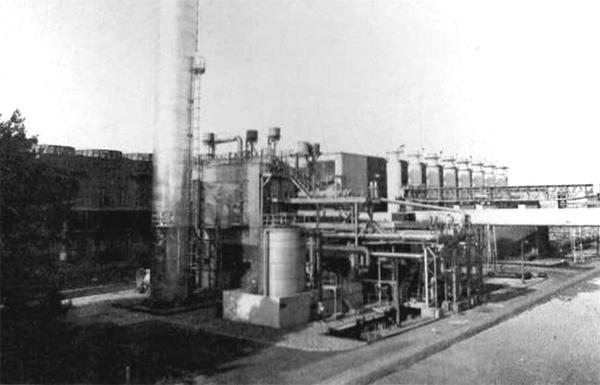
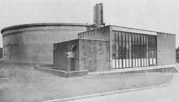
- Demineralised water: For special purposes such as aero engine icing trials and the
direct injection of water into experimental engine compressors, very pure water is
required and N.G.T.E. has an ion exchange plant to demineralise the
water used in these services. The ion exchange plant is supplied with water already
softened in the Starvation plant, the process removes all minerals and silica in addition
to the reduction of hardness and alkalinity already achieved in the Starvation plant.
Chemical treatment is used to restore phosphate balance as well as to scavenge the
oxygen and carbon dioxide content.
The installation is sized to match the distilled water demands of the boiler plant and the
capacity is 1500 gal/h, although there is a maximum production limit of 22,400 gallons of
pure water in a twenty-four hour period due to the need to reactivate the ion exchange
resins. The output can be stored for very short periods in a special storage tank at the
Boiler House whilst the plant is reactivated.
There is a separate circuit for the distribution of demineralised water, the main 25 gal/min
pump discharge into a 3 inch bore main to supply the Boiler House,
and there is a 2 inch spur for Cells 1 and 2, and 1 inch
supplies to Cell 3,
Cell 3 West and the
Admiralty Test House; the demineralised water circuit is
shown in Figure 5.8 and Figure 5.11 shows the plant pictorially.
|
|
Fig. 5.11 The demineralized water and starvation treatment plant
|
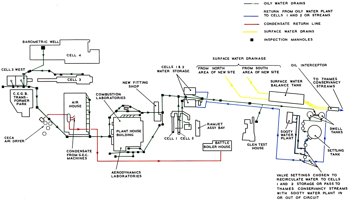
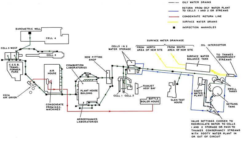
5.6 Water drainage and effluent treatment
The effluent from the N.G.T.E. site can be separated into two
categories :-
- Clean surface drainage water
- Oil and soot contaminated effluent.
The surface drainage system which drains water from buildings, rainwater pipes,
road gullies, etc., joins two 18in manifolds, one of which collectrs from the area north of the
Air House, including Cell 3,
Cell 3 West and
Cell 4 area, whilst the other collects from the southern half of
the N.G.T.E. New Site. These drains feed into an open brick storm tank of 750,000 gallons
capacity, which absorbs flood water which would overload the clearwell weirs, and where the water is either
trapped and skimmed so that foreign matter such as oil and grease is removed, or, if free of contamination
allowed to pass through clearwell weirs to the streams which are under the jurisdiction of the
Thames Conservancy Board. This water is closely scrutinised to conform to the Board's standards, which are
that the pH value shall be between 6 and 9, the total solids in suspension not to exceed 30 ppm and the
biochemical oxygen demand not to exceed 20 ppm. Also no toxic substances, oil or greases,
are permissible. Special precautions are taken to treat the water in the storm tank should the
surface water for any reason become contaminated.
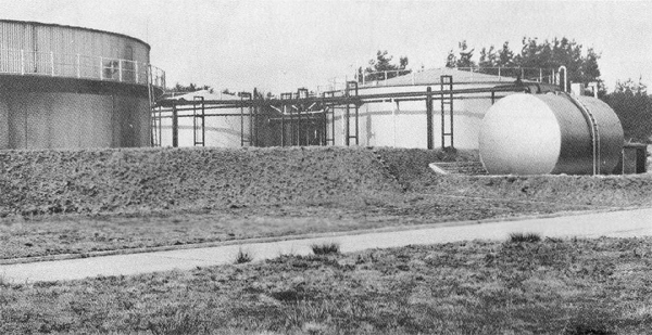
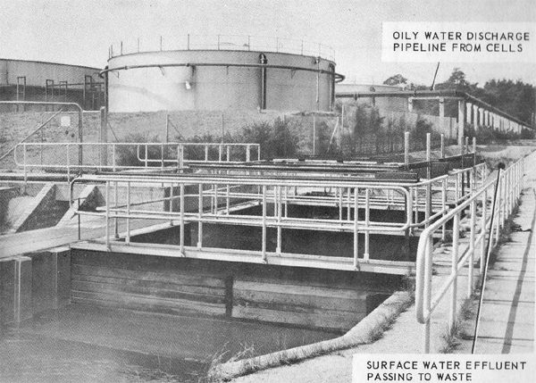
The oily water from the test cells and other plant is drained into two
300,000 gallon dwell tanks by way of an 18in bore manifold. The water is allowed to stand in these
two dwell tanks so that the emulsion can be stabilised. The effluent is then pumped automatically
by float controlled pumps into a settling tank of one million gallons capacity. The water effluent
is allowed to remain in this tank for sufficient time for the oil to surface, when it is skimmed
off into troughs and transferred to a 20,000 gallon kerosine dump tank for disposal. The clean
water from the settling tank is pumped automatically at a maximum rate of 30,000 gal/h via the surface water
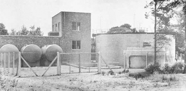
clearwell weirs, where its quality can be monitored, to the Thames Conservancy streams. Figure 5.12
and 5.13 show views of the oil sooty water dwell tanks and clearwell weirs and Figure 5.14 shows the
site drainage circuit.
|
|
Fig. 5.12 General view of oily sooty water receiving tanks
|
|
|
Fig. 5.13 N.G.T.E. water effluent disposal plant
|
|
|
Fig. 5.14 Circuits for N.G.T.E. test cell drainage system
|
When the effluent is sooty as well as oily, the output from the settling
tank which has had the oil removde is re-cycled through a sooty water flocculation plant for processing
instead of passign to the Thames Conservancy streams. In this plant the effluent passes into a clarifier where
flocculating additives, Superfloc 16 and Aluminium Sulphate, are introduced. These materials cause the
sooty particles to become negatively charged thus creating greater mutual affinity with each other and a
heavy flock forms so that the particles sink to the base of the clarifier where the sludge is removed.
The clear water from the clarifier is returned to the
Cells 1 and 2 storage tanks for reuse or, when these
reservoirs are full, the excess drains away to the Thames Conservancy streams.
The maximum operational capacity of the sooty water treatment plant is 30,000 gal/h
and its operation is fully automatic. The sludge water is filtered down to 5 microns before it
passes to drain leaving a very small volume of dry carbon waste. The sooty water treatment plant is
shown pictorially in Figure 5.15.
|
|
Fig. 5.15 The sooty water treatment plant
|
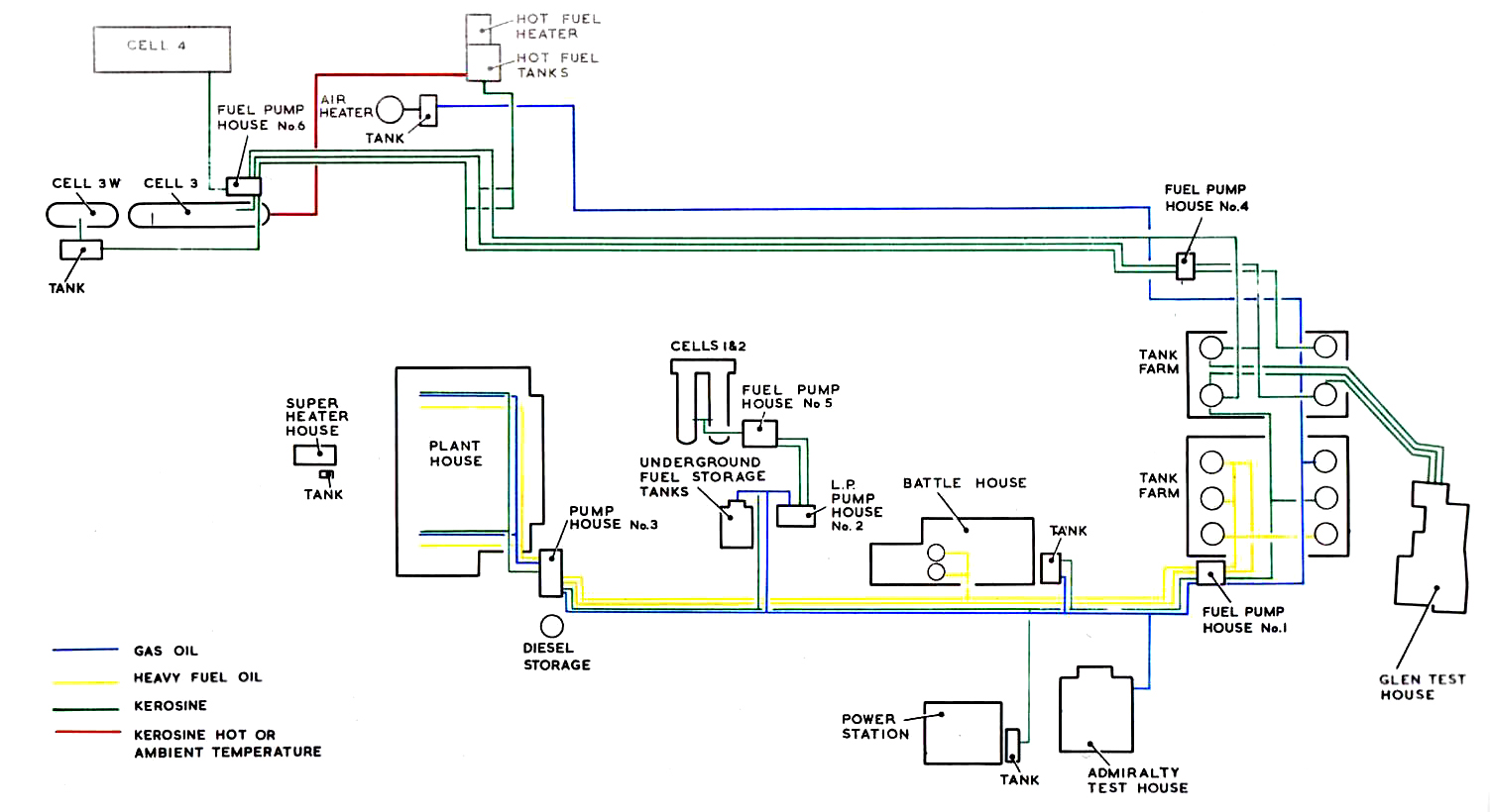
5.7 N.G.T.E. fuel supplies
N.G.T.E. has its own fuel storage tank farm and pumping arrangements
on the Old Site. Separate systems supply fuel to the small test cubicles which are not described in this
publication.
On the New Site Avtur, Avtag and Diesel fuel can be stored and pumped to local tanks
or fuel systems according to need. The New Site system also provides the heavy fuel used in the
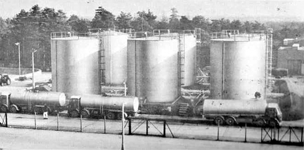
boilers to generate steam. Figure 5.16 shows the New Site fuel tank farm pictorially.
|
|
Fig. 5.16 N.G.T.E. New Site fuel tank farm viewed looking east
|
The New Site tank farm has two bunds, one having six 80,000 gallon tanks and the
other four 80,000 gallon tanks. The tanks in the smaller bund (Nos 107, 108, 109 and 110) store aviation
kerosine (i.e. Avtur with the exception of tank 110 which may store Avtag) whereas the tanks in the
large bund (Nos 101, 102, 103, 104 and 106) store heavy fuel and gas oil.
Aviation kerosine, to reference standards when used for engine performance trials,
is pumped through two six-inch lines to Cell 3,
Cell 3 West and
Cell 4; a third 6 inch line is available for spill or
flushing duties. Separate lines supply fuel to the Glen Test House,
Cells 1 and 2,
Plant House,
Power Station,
Admirality Test House and the
Battle Test House.
The six tanks in the larger bund supply four different fuel pipelines, two of 6
inch and two of 3 inch diameter. The 6 inch lines normally carry heavy fuel oil of 3000 second
Redwood viscosity and these pipes are externally lagged and stream trace heated.
The two 3-inch lines carry either kerosine, gas-oil, or wide-cut gasoline and
connect with the Plant House,
Power Station and
Admirality Test House; there are also cross-connections
with the underground storage tanks in Cells 1 and 2. A
further 1.5 inch pipe supplies gas-oil to the
Cell 3/
Cell 4 air heater.
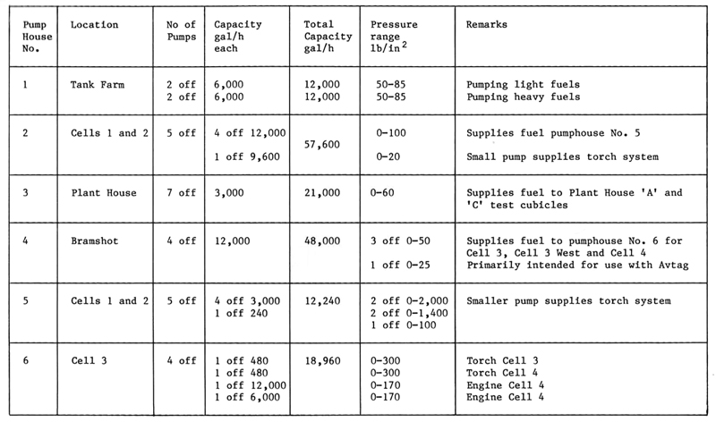
Figure 5.17 shows the permanent pipework installations but no attempt is amde
to show the individual test area systems. Detailed information on these is available in a number
of N.G.T.E. publications (e.g. Cells Engineering handbooks). Table 5.4 details the
pumping capacity of the six fuel pumphouses on the New Site. There are other pumps, but these are classified
as part of the individual test area systems.

|
|
Fig. 5.17 Layout of New Site fuel distribution system
|
Table 5.4
New Site Fuel System Pumping Capacity
© Procurement Executive, Ministry Of Defence
|