|
 | Research Rig Facilities |
30. Research Rigs and Equipment
The N.G.T.E. 1969 research programme is spread over a number of themes, all of which require large
test rigs of varying complexity so that basic problems can be investigated. Most, although not all of these rigs,
use the high pressure air and associated laboratory facilities that have already been described in Sections 2 and 4.
It is not possible to describe every one of the research rigs in detail but in order to present a comprehensive survey
of the N.G.T.E. capability for gas turbine testing, the larger and more complicated equipments are listed.
In addition to full-scale engine testing, research is undertaken in the subjects of :-
- Powered lift, circulation control and noise.
- Aerodynamics of compressor and turbine machinery.
- General engine research.
- Combustion, chemcial physics and instrumentation technology.
- Science of materials.
- Engine performance and feasibility studies.
31. Circulation Control Rigs
At N.G.T.E. research is being directed towards finding a technique which will produce high lift
coefficients for a small expenditure of jet momentum. Following a successful development of the original idea of "Jet Flap",
a system of "Circulation by Blowing" is being developed. In this system blowing slots are inserted into the surface of the
rotating cylinder so that the energy in the emergin het flow is used to re-energise the boundary layer of the air
on the cylinder surface and in this way it is possible to control the main stream separation point. The lift coefficient
is controlled by varying the momentum of the air emerging from the slots in the cylinder surface.
Work at N.G.T.E. on circulation control is carried out on both mobile and static test installations. The
main rigs are (a) the No. 133 static rig and (b) the No. 136 mobile rig.
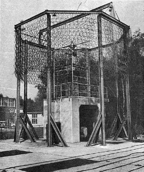
- (a) The static rig has been designed to enable hovering characteristics of circulation controlled rotor blades to
be measured. The rig is basically a compound wound d.c. electric motor producing 635 bhp at 1200 rev/min with an input
of 1,350 amps at 525 volt potential. The motor speed is constant when set, irrespective of the load. The motor is housed in
a concrete blockhouse 10ft high, on whci his mounted a structural steel tower in two parts, giving a total rig height of
22ft. A shaft drive system transmits power from the motor to the top of the tower, at which point air supplies from the
Old Site Compressor House are also available. Figure 97 shows the circulation control static rig pictorially.
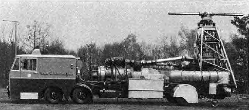
- (b) The mobile rig enables the characteristics of circulation controlled rotor blades to be measured with varying ratios
of vechicle forward to blade rotational speed. As shown in Figure 98, the rig is based on a Bedford VAL coach chassis with a
Leyland 150 hp engine. The chassis carries a subframe which is the base for a Rolls-Royce Avon Mk 204 turbo-jet. The
Avon produces 21 lb/s of compressed air, beld from the compressor 7th stage, at a maximum pressure ratio of 4:3:1 and
maximum temperature of 200°C. The Avon also provides up to 2,000lb of thrust which can be directed rearwards to assist
vehicle motive power or angled forwards to assist braking.
- The rig is independent of service supplies having two air compressors and a 115 volt 400Hz alternator driven from
the Leyland engine, a petrol engine generator unit providing 250 volt 50Hz, and a 24 volt d.c. supply from batteries.
- At present the rig is set up with the bleed air driving a vertically mounted Rolls-Royce Dart turbine producing 600 hp
at 1,200 rev/min.
|
|
Fig. 97. Circulation control static rig No. 133.
|
|
|
Fig. 98 Circulation control mobile rig No. 136.
|
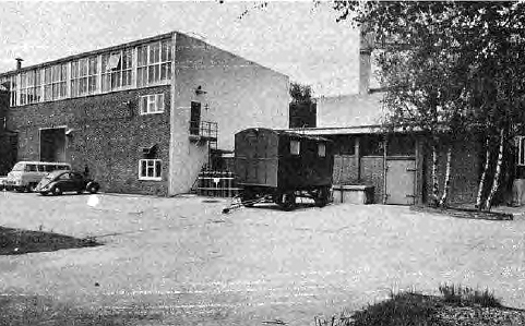
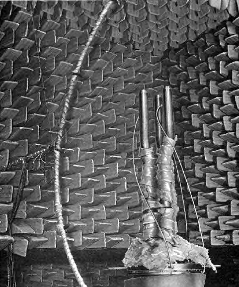
32. Noise Research Rig
For some years N.G.T.E. has been investigating the problems associated with aircraft and gas turbine
engine noise and they have developed and built an anechoic chamber with jet blowing facilities. This anechoic chamber
enables jet noise studies to be conducted under acceptably free field conditions. Noise measurements can be made
at distances of at least two wavelengths from the source of the noise. The test chamber is constructed so that all internal
surfaces have very low acoustic reflectivity; the rig is designed to ensure that the induced air mixes with the jet
source such that it is truly representative of operating conditions in the open air.
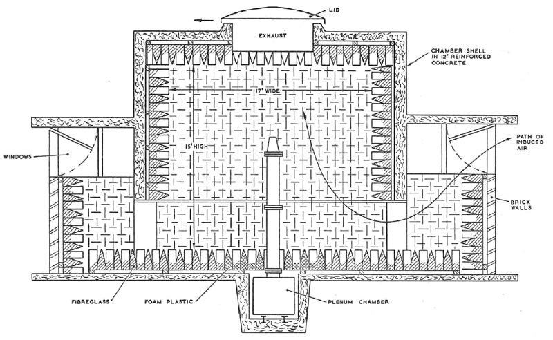
The facility incorporates means of (a) measurement of thrust from the jet nozzle, (b) heating the
primary nozzle air supply to 1,200°C, (c) producing Schlieren pictures with film camera and closed circuit television,
(d) traversing of a multi-microphone array. Two additional air supplies provide slipstream and secondary air services.
Compressed air is supplied from the Old Site Compressor House and the limiting flow of 56 lb/s at 4:1 pressure ratio
dictates that model-scale nozzles within the size range of 3 to 28in2 throat area may be tested. The
size of the chamber, a minimum internal dimension of 15ft, dictates that the lowest frequency, taken at a distance
of not less than two wavelengths from the source is 300Hz. An air main duct, below floor level, traverses the chamber on
the centreline. It contains the three air mains, one of 12in diameter for the jet nozzle supply and two of 6in diameter
for other necessary services. The 12in main is able to deliver air at either 4:1 pressure ratio (nominal mass flow
56 lb/s) or 10:1 pressure ratio (nominal mass flow 7 lb/s). The two 6 in mains are able to deliver air at 4:1 pressure ratio.
Figures 99, 100 and 101 illustrate the anechoic chamber noise rig installation.
|
|
Fig. 99. Anechoic chamber building.
|
|
|
Fig. 100. Inside anechoic chamber.
|
|
|
Fig. 101. Section through anechoic chamber.
|
A connection is provided between the duct and Control Room by a 6-way G.P.O. cluster and instrumentation
cables and pipes are carried in this cluster.
That part of the duct which lies within the anechoic chamber is furnished with a bedplate for mounting
the jet nozzle rig.
The two walls of the chamber above the bedplate are pierced by slots 6in wide to enable the
Schlieren system to be erected in such a way that no optical components have to be installed in the anechoic area
thereby avoiding acoustic reflections, also, for the same reason there are no fixed artifical lighting
fittings in the chamber, and portable lighting and heating must be brought in as and when required.
Intercommunication points are provided at strategic locations; there are also service air
and domestic water supplies in the subterranean duct.
33. Test Rigs to establish Mechanical Properties
Research into the mechanical properties of materials and components working under gas turbine
conditions is carried out at N.G.T.E. in the three main test rigs, they are (a) the burst rig, (b) the slow strain
tensile plotter, (c) the fatigue cycling rig.
|
(a)
|
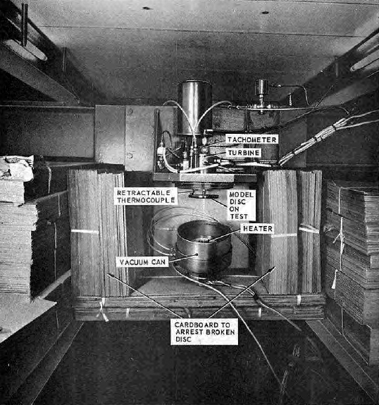
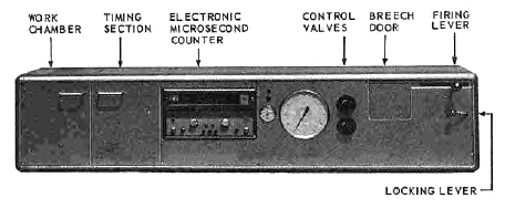
The burst rig exists for bursting model turbine discs to establish the failure speed, centrifugal loading
and the material integrity.
Most of the work carried out on material evaluation is based on discs ranging from 4.8in diameter (steel)
to 6.0in diameter (titanium) weighing approximately 2lb.
The versatility of the rig is shown by its capability of spinning on one hand, light discs approximately 3in
in diameter and weighing only a few ounces to speeds in excess of 150,000 rev/min, and on the other, discs of 11½in
diameter having weights of the order of 12lb to speeds of around 40,000 rev/in.
The disc under test is mounted in a vaccum in order that the driving power required is reduced and the frictional
heating effect minimised.
The facility, show in Figure 102, is also used for conducting tests at elevated temperatures by immersing
the disc in an electrically heated hot-air stream for prolonged periods. Disc temperatures of 700°C can be achieved.
|
|
(b)
|
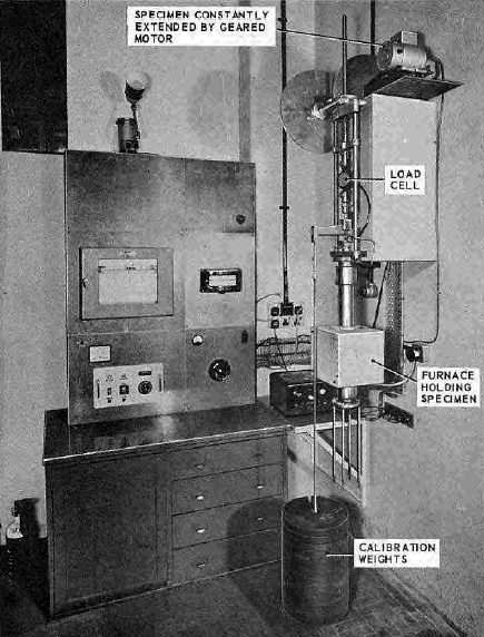
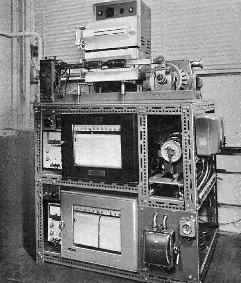
The slow strain rate tensile plotter has been developed to perform tensile tests on materials of interest
in the aero-engine compressor and turbine disc field. The equipment provides means of plotting out the complete stress strain
curve of a material from no load to the fracture point.
The curves thus obtained are used in conjunction with a computer programme to correlate the failure speed
of a disc spun on the burst rig.
It is also possible to test the tensile specimens up to temperatures of 700°C for correlation with
discs spun at elevated temperatures. This rig is shown in Figure 103.
|
|
(c)
|
The high speed fatigue cycling rig is shown in Figure 104. It is at present under development for
investigations into the crack initiation and propagation field for aero-engine disc materials.
|
|
|
Fig. 102. High speed bursting rig.
|
|
|
Fig. 103. Slow strain tensile plotting rig.
|
|
|
Fig. 104. The high speed fatigue cycling rig.
|
34. Engine Research Rigs
The major rigs for investigations into engine problems are (a) the 12in diameter intake test rig
which is installed in Cubicle C3 of the Plant House building and
(b) the propelling nozzle rigs installed in the Cathedral cubicle, also in the Plant House.
|
(a)
|
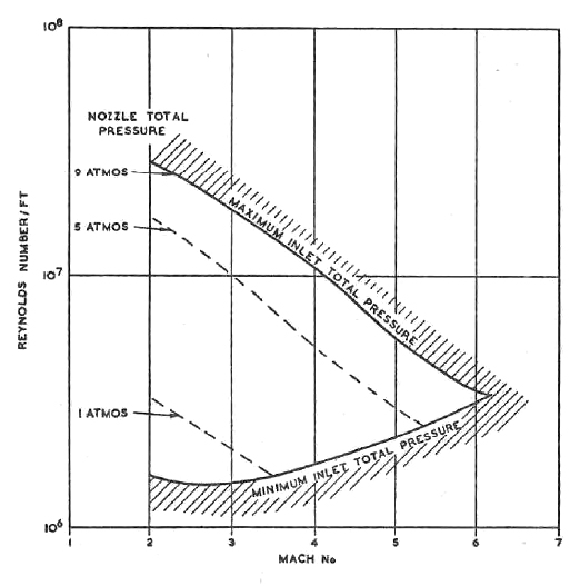
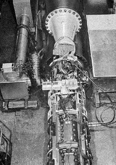
The 12in diameter continuous running intake test rig has been designed to test supersonic air intakes
with variable geometry over a range of Mach numbers and Reynolds numbers. Fixed axisymmetric nozzles are available
for Mach numbers of 1.9, 2.2, 3.0 and 4.0.
The rig has a semi-closed jet; this provides a compromise between the better performance obtainable
with a closed jet rig and the larger ratio of model size to jet size which can be obtained with an open jet. Large windows
are available for flow visualisation and these can be located at several different positions along the length of the
working section.
The working section is stressed to a pressure level that permits test Reynold numbers per foot of u
to 2.7 x 10⁷ at M=2.0, 1.6 x 10⁷ at M=3.0, 1 x 10⁷ at M=4 and 5.1 x 10⁶
at M=5.
Model intakes can be mounted on pitching or yawing machines for tests at up to approximately
15° of either pitch or yaw.
Figure 105 shows the intake test rig's working range whilst Figure 106 shows the rig installation.
|
|
(b)
|
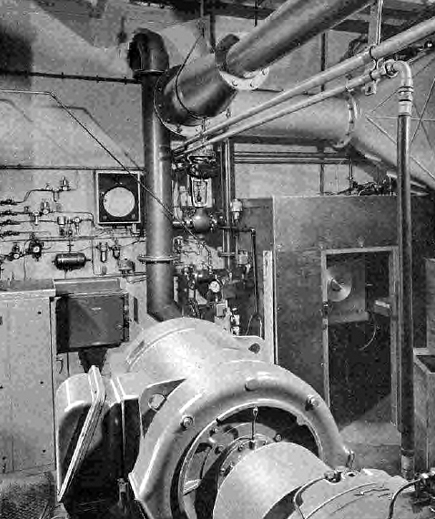
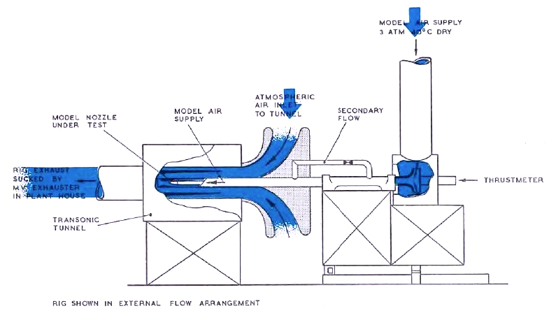
The propelling nozzle rigs, one of which is shown diagrammatically in Figure 107, are both situated in
the Cathedral cubicle of the Plant House and are capable of accurately
measuring the thurst and drag of scale models of engine exhaust nozzles in either static conditions or with
a representative external flow (subsonic, transonic or supersonic).
The test nozzle is mounted on the end of a sting which can have either single or two streams of
separately metered and controlled airflow. The total airflow through the test nozzle which is alreadys supplied
dry, is approximately 2lb/s/atm and can operate at up to approximately 5 atm during quiescent tests. An exhaust diffuser
enables pressure ratios of up to about 30 to be obtained.
For tests with external flow the same rate of airflow applies but with a maximum pressure of about
3 atm. The nozzle pressure ratio is then governed by the selected Mach number.
On both rigs the external flow at conditions up to transonic speeds is obtained by using a slotted
nozzle. The older rig has a circular cross section, whereas the newer one has an octagonal section which enables flow
visulisation of the shock system. For supersonic conditions, fixed Mach number liners may be inserted inside the
circular slotted nozzle. Air at approximately ambient pressure is used for the external flow and has to be supplied dry
for Mach numbers in excess of 0.9
|
|
|
Fig. 105. Operating range for N.G.T.E. intake test rig.
|
|
|
Fig. 106. Intake test rig.
|
|
|
Fig. 107. Two steam propelling nozzle rig.
|
35. Rigs and Equipment installed for Combustion and Chemical Physics Experiments
Combustion research has been a very important part of the work of Pyestock ever since
the gas turbine was first developed. In the main, combustion rigs use the services which have been
installed in the Plant House and the Old Site Laboratories
described in paragraphs 28 and 29. The most important rigs are :-
|
(a)
|
The hot jet facility: This rig is suitable for testing materials and components in
hot supersonic velocities. It consists of a ramjet burner supply a water cooled convergent-divergent nozzle
of Mach number 1.7 at atmospheric pressure and 1000°C, the nozzle having a throat diameter of 10in. Nose cones
up to 2in diameter provide typical investigations.
|
|
(b)
|
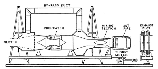
Full scale by-pass reheat rig: This is ideally suitable for jet pip investigations; the
essential equipment comprises a Sapphire VII preheater, ducting giving by-pass simulation, and thrust equipment
of 10,000 lb capacity. The rig is installed on 'B' bed in the Plant House
No. C4 Cubicle. It includes variable nozzle control, colour cine photography, pressure/temperature detection and
recording, and exhaust gas sampling analysis. The rig is also used for reheat investigations for which
special techniques have been developed; the rig arrangement is shown in Figure 108 and the installation is
shown in Figure 109.
|
|
(c)
|
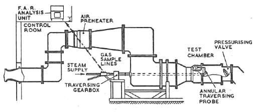
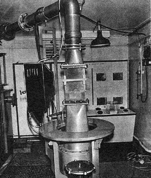
General purpose combustion rigs: Three separate rigs have been installed in the
Plant House C5 Cubicle, one of which uses the 1-5 MW electric preheater
described in paragraph 28, the other two rigs using vitiating preheaters. The capacity of these latter rigs is
150 lb/s at temperatures up to 400°C; the pressurised combustion rig is shown in Figure 110. These rigs have
special traversing gear for measuring combustion chamber exit temperature, pressure and fuel-air ratio;
the latter system is shown in Figure 111.
|
|
|
In addition, on the Old Site, a hack combustion chamber installation permits three of the
beds to be fed with air at 500°C at a flow rate of 30 lb/s and a working pressure ratio of 4:1.
|
|
(d)
|
Thermocouple development: Two rigs are installed on the Old Site, one having a capacity
of 900°C and the other 1,700°C at atmospheric pressure.
|
|
(e)
|
Flow visualisation rig: Water analogy is used to enable the overall and detail flow patterns in
a gas flow system to be investigated by direct observation. The rig comprises a water tunnel and a water
channel. Solid, air bubble and dye tracers are used to illuminate the flow patterns so they can be photographed.
The rig is shown in Figure 112.
|
|
(f)
|
Model combustion chamber rig which permits studies of primary zones: This rig uses the
Alley 30:1 air supply described in para. 29 and has a limited capacity of 1 gramme of air/atm/s (approximately
5 ft/s velocity). Uniform flame compositions are produced from vapours or sprays composed of singly selected
droplets; the size of the driplets can be varied over a range of 20 to 100 microns. The rig is equipped to
measure flame radiation and flame temperature as well as sampling and analysis of the products of combustion.
The inlet air temperature can be raised to 400°C by an electric pre-heater.
A second model combustion chamber primary zone rig to be commissioned shortly will
allow primary zone velocities of 60 ft/s to be produced; this rig will use an acoustic atomiser. It is equipped
with a dilution zone which will permit the study of reactions such as the formation of oxides of nitrogen
and the combustion of soot. The rig will be supplied with air at 50 atmospheres pressure and a
temperature of 900°C. The rig capacity will have a flow rate of 22½ grammes of air 'atm's.
|
|
|
Fig. 108. Layout of bypass reheat test rig.
|

|
|
Fig. 109. Bypass reheat test rig.
|
|
|
Fig. 110. Pressurised combustion chamber test rig.
|

|
|
Fig. 111. Gas sampling system for fuel/air ratio meter.
|
|
|
Fig. 112. Flow visualisation rig.
|
36. Rigs for Research into Gas Turbine Materials
Research intro engineering materials that will withstand high temperature stress conditions
has always had an important role in gas turbine development. For many years the absence of suitable materials for
turbine blades and other major components prevented the development of the gas turbine engine, and the importance
that discovery and development of new materials had in the evolution of the jet engine has already been declared by
Whittle and other pioneers. At N.G.T.E. special rig equipment has been developed to continue further research into
the science of materials. The most important rigs are :-
|
(a)
|
Vaccum induction melting furnace: This provides a facility for heating moulds under vaccum conditions
and is especially important for directional solidification in a vaccum. The furnace has a maximum temperature of
1,500°C and is capable of being charged with specimens up to 25lb in weight. The furnace has high frequency induction
heating and the electrical input is 4kVA and frequencies of 8,000Hz.
|
|
(b)
|
Vacuum brazing furnace: This provides a facility for applying pressure loads to specimens and joints
whilst they are being pressure welded, or diffusion bonded. The furnance has a maximum temperature of 1,750°C which
is achieved by resistance heating; the electrical input for this purpose ing 7kW. The pressure is applied through a
1½in diameter ram which has a 3in travel; the maximum load being 500lb.
|
|
(c)
|
Vacuum creep test rig: A battery of four Vacuum Creep Test Rigs are available, and these are shown in
Figure 113. These machines allow creep tests under vacuum conditions or in different inert atmospheres at temperatures
up to 1,600°C. The maximum load which can be applied to the specimen is one ton. The hot thermal zone for
the machines is 4in long and 1in bore in size; heating is carried out by welded molybdenum resistance elements.
|
|
(d)
|
The ballistic impact test rig: This provides a facility for firing projectiles at hot specimens. The range
of bullet size varies between 1/16in and 3/8in in diameter, and the maxiumum projectile velocity is 1,000 ft/s; ball bearings
are frequently used for bullets. The impact speciments are normally 2in x 1in x ½in in isze, and they can be
pre-heated to a maxiumum temperature of 1,200°C. This rig is shown pictorially in Figure 114.
|
|
(e)
|
The crack propagation test rig: This is shown in Figure 115. It has a maximum working temperature of
800°C and specimens can be vibrated at frequencies varying between 10 and 2,5000 cycles/min. The crack growth is
detected by the change in resistance that occurs as the crack is propagated; the stress at the base of the crack
and the crack length are recorded continuously by automatic means.
|
|
(f)
|
Fluidised beds for thermal shock testing: Thermal shock conditions are produced in immersing
specimens of different materials, alternatively, in hot and cold beds of fluidised zircon sand. The hot bed has a resistance
heating element fitted to the walls of the fluidised bed container so that the sand in direct contact with the resistance
element is constantly heated and under the effect of the fludised bed the hot sand particles move continiously towards
the specimen which is located in the centre of the bed, replacing the cold particles which have given up their heat.
The cold bed has a water jacket around its outer walls and the sand adjacent to the specimen is held at ambient temperature
as heat is transferred to the outer walls under the effect of the fluidised bed. By immersion in both the hot and cold beds, the
speciment is subjected to thermal shock; the permeability of the fluidised bed may be varied to give control of the thermal
shock experiment. The hot zone is 4in diameter and has a maximum temperature of 1,200°C.
|
|
(g)
|
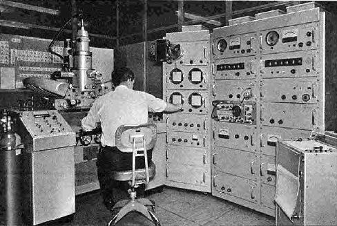
The electron probe micro-analyser: This is fitted with a scanning electron microscope which is capable of analysing
materials in the micron scale and detecting elements in the "Periodic Table." The instrument is capable of identifying
particles as small as 1u inch in size, and all elements above Boron (No. 4) in the Periodic Table can be identified. The
scanning attachment produces three-dimensional-type images of surfaces of fracture. The equipment is shown in Figure 116.
|

|
|
Fig. 113. Battery of vacuum creep machines.
|
|
|
Fig. 114. Ballistic impact test rig.
|
|
|
Fig. 115. Crack propagation test rig.
|
|
|
Fig. 116. Electron probe micro analyser.
|
© Procurement Executive, Ministry Of Defence
|