 | Introduction - Growth Of The NGTE |
1.1 Introduction
The engine test facilities at the National Gas Turbine Establishment (N.G.T.E.) Pyestock were constructed to
allow the testing of gas turbine and ramjet engines to be performed on the ground under controlled conditions simulating
flight altitude and aircraft forward speed. The provision of the facilities provides an alternative way of proving partially
developed engines without recourse to flight testing which is frequently limited in scope and exposes newly designed and most
valuable equipment to a variety of risks.
The N.G.T.E. facilities cater for the testing of individual components and sub assemblies
as well as engines and intakes. Component test facilities are described in Section 4 where an accoutn is also
given of the aerodynamic and combustion rigs whilst the engine test facilities is dealt with in Section 3.
Details of the facilities for the testing of materials associated with gas turbine engines are given in Section 5
together with information on some of the more important experimental plant.
In order to meet the test requirements of large size engines considerable quantities of compressed air,
cooling water and fuel have to be supplied. An extensive suction service to simulate altitude conditions is also needed.
The plant providing these services is described in Sections 2 and 6.
The electrical power consumed in running the test plant is correspondingly large and financial considerations
impose a limit on the total power that can be consumed. This limitation demands that testing is carefully programmed to ensure
that the maximum demand figure is not exceeded. Where necessary N.G.T.E can generate a certain amount of its
own electricity and detials of this facility and of the electrical power distribution network are contained in Section 6
In more recent years the noise problem in aircraft has led to an increase in noise research with the result that the
N.G.T.E facilities have been extended to include both an absorber and an anechoic test bed capable of full scale noise
investigations the noise facility is described in Section 7.
A brief outline of the history of the N.G.T.E. and of the growth in the test facilities is given later in
this Section.
Of necessity the contents of this brochure are of a general nature, general enquires and requests for further information
should be addressed to The Director, National Gas Turbine Establishment, Pyestock, Farnborough, Hants.
1.2 The Growth Of The N.G.T.E.
The National Gas Turbine Establishment at Pyestock was formed in 1946
from the earlier wartime organisation Power Jets (Research And Development) Ltd. The first test facilities
were provided to meet the needs of component testing and consisted of air compressing equipment and an associated test
house. The early equipment known as the Old Site is still in use and is described in more detail in
Sections 2 and 4.
With the continued development of the gas turbine engine the need for more elaborate component test facilities was forseen
and these were supplied by building the Plant House component test facilities which
are described in Section 4.
In parallel with this development the need for a full scale engine test facility which could simulate altitude and
forward speed conditions was recognised and work began on the design of Cells 1 and 2.
These cells were subsequently built and commissioned in 1952/4. Cells 1 provides
a means of blowing supersonic air at an engine to simulate aircraft forward speed. This arrangement is known as free-jet testing
and enables engine intake performance to be studied. In Cell 2 the test engine
is connected directly to a chamber which is fed from the main compressed air supply in a radially inward direction so that
thrust forces are balanced. This arrangement is known as Connected Testing and is used for engine integrity and
combustion chamber tests. Altitude simulation in both cells is achieved by the use of air driven ejector plant. The range of test
conditions which can be attained is given in Figure 44 and the plant is described in more detail in Section 3.
As aircraft size and performance increased, the need for facilities with corresponding greater range and flexibility arose,
and so more sophisticated air processing equipment was needed to correctly simulate high and low temperature operating
conditions. Cell 3 and the main Air House
compressor/exhasuter plant were provided in 1955 to meet these needs. The air supply machinery is described in
Section 2. The Cell 3 performance envelope for connected tests is
given in Figure 51 and a more detailed description of the cell plant including the associated air heating and cold air
processing plant appears in Section 3, para. 14 to 18.
The arrival of supersonic air travel and the subsequent development of sophisticated air intake equipment
brought the need for a test facility that could simulate supersonic airflows over a wide speed range to enable the interaction
of intake and engines to be studied under rapidly changing conditions. Cell 4,
a free-jet cell, was built and commissioned in 1966 to meet this requirement. The Cell 4
equipment includes a 25 square ft variable Mach number supersonic nozzle and a high speed pitching and yawing capability. Further
details of the Cell 4 plant are given in Section 3 and
the performance envelope is shown in Figure 68.
In parallel with the building of Cell 4, additional suction
facilities were provided with the installation and commissioning of No. 9
exhauster plant described in Section 2, para 5. This was followed in 1968 by the installtion of
No. 10 exhuaster plant, described in Section 2, para 6,
which further extended the range of altitude conditions that can be simulated.
With the advent of the so called 'new technology' engines (Rolls-Royce RB211) for aircraft such as the Lockheed 'Tristar',
the requirement arose for a facility capable of testing under altitude conditions very large diameter power plants of high
thrust but low inlet and exhaust velocity. To meet this requirement Cell 3 West
was designed and built, final commissioning taking place in 1969. In this cell air supplies for the engine are induced
from atmosphere by suction applied at the engine exhaust end. The atmospheric air is drawn through a large capacity inlet air
cooler refrigerated by aqueous ammonia; the Cell 3 West plant is described in more
detail in Section 3, para. 19 and 20, and the performance envelope is given in Figure 62.
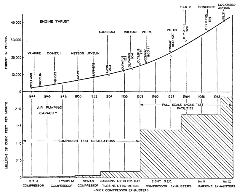
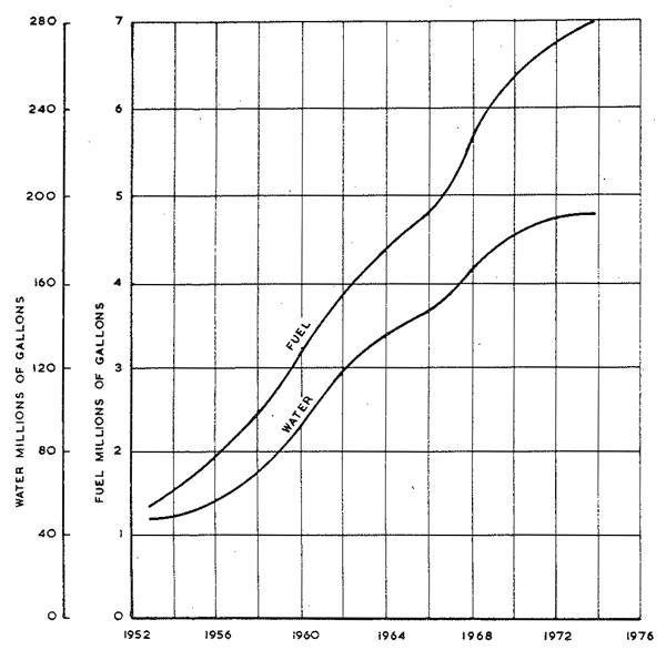
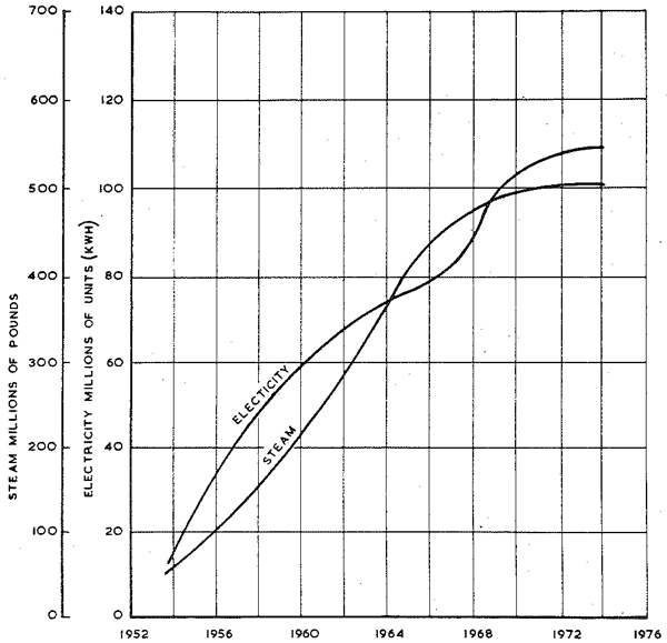
The expansion of the N.G.T.E. test facilities is illustrated in Figures 1 to 3 which plot the growth
in the installed air pumping capacity and associated services over the years. Also shown in the growth in electricity consumption,
the amount of steam generated, fuel consumption and water consumption.
|
|
Fig. 1 Growth of N.G.T.E. Engine Testing Plant, 1944 - 68
|
|
|
Fig. 2 N.G.T.E. fuel and water consumption
|
|
|
Fig. 3 N.G.T.E. electricity and steam consumption
|
© Procurement Executive, Ministry Of Defence
|